1
17
submitted 3 days ago by [email protected] to c/[email protected]

Related, relevant advice on SSD reliability (dated 2015, still relevant? inquiring minds want to know): https://www.anandtech.com/show/9248/the-truth-about-ssd-data-retention

2
23
submitted 1 week ago by [email protected] to c/[email protected]
3
9
submitted 1 month ago* (last edited 1 month ago) by [email protected] to c/[email protected]

Just working on my recent electronics project and I needed two temperature sensors for it. This time around I didn't feel like making a full PCB from KiCAD and wanted to keep things simple with a 1/2 size solderable breadboard.

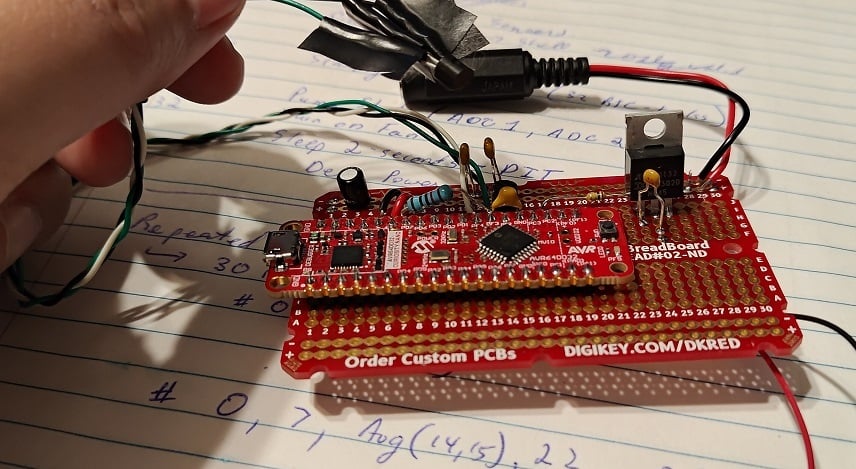
As usual, I'm using an AVR DD (this time: a curiosity nano devboard) for simplicity. (I expect to need the 32768 Hz clock crystal, so a PCB with said clock would be nice. Otherwise, the DIP package is available). The overall circuit is pretty simple, but the topic of discussion today is the MCP970X series temperature sensor.

https://www.microchip.com/en-us/product/mcp9701a

At this point I do recommend people to read the documentation.

The gist is that you simply apply 3.1V to 5.5V between Vdd and Gnd. Vout will have some amount of startup time, and eventually output 400mV + (Temperature-in-C * 19.5mV). For example, my room temperature is ~24C right now and the voltage output is ~920mV.

(There's clearly errors in my ADC but I'm saving that for later... this device is supposed to be outputting 876mV given the room's temperature)


With a ~6uA expected current, this device is power-efficient enough to run from most MCU pins. AVR DD's 50mA-per-pin is overkill, but more importantly, a through-hole design like mine seemingly has substantial inductance on all wires.

The datasheets claim a startup time of 0.8ms. Alas, when I soldered on the MCP9701 and turned on the GPIO-pin, it took over 20ms (!!!) before the oscillating signal finally calmed down and settled upon the room temperature reading.

To counteract this parasitic inductance, I've added a 10kOhm resistor and a 10nF capacitor out of my through-hole kit. (E12 resistor kit and E6 capacitor kit). With 220us of startup time now on the GPIO pin and with only 500uA max current going to Vdd... there is no more "ringing" anymore and life is good!

EDIT: I should probably note that my goal was to return to 0.8ms startup time, like the documents suggest. 10kOhm was chosen as 500uA (5V) to 250uA (after charging to 2.5V) is a magnitude more current than I need and is a decent starting point. 10nF was chosen to pair-up with this to give me startup time in the 100us range but not over 800us (I don't want to be "slowed down" by the charging capacitor, so I want the Vdd charge to be faster than 800us claimed startup time). It should be noted that a 5V over 1000us curve was claimed as a 800us startup in the MCP970x documents if you read all the graphs.


Moving forward, my last task is that of calibration. The on-board ADC of the AVR DD is apparently quite accurate, but the Vref of the microcontroller is +/-4% (!!). With a +/- 2% accuracy of the temperature sensor, there is some calibration I should do.

The ADC errors + Vref errors are expected to just be linear. The temperature-sensor's error is quadratic however. In both cases, I don't want to overcomplicate things, so I'm planning on just adding a constant-offset to the mV reading to shift it to the correct spot.


All in all: pretty standard Analog-to-digital conversion issues here. But I figured it'd be a good discussion topic for beginners.

4
12
submitted 1 month ago by [email protected] to c/[email protected]

Modern AVR has a wide variety of Timers (TCA, TCB most commonly, but TCD, TCE, and TCF are uncommon and specific to particular AVR chips).

This can make choosing a AVR DD vs AVR EA vs AVR EB vs AVR DA a difficult choice, especially if you're trying to use timers to their greatest extent possible.

This blogpost covers a basic idea of what the different timers offer.


The blogpost is short enough. I feel like what I can add is to highlight the difference between:

  • Timers -- A background count++, a comparator of count vs some pre-configured values, and then likely an output pin that changes based off of these configurations. Consider this an MCU output. Almost everything listed can be used as a timer.

  • Counters -- Counter functionality is an MCU input. Many protocols, such as Servos, PWM, pulse-train decoding requires a variety of pulse-frequency-modulation, pulse-counting, or wide variety of other kinds of common tasks. "TCB" may be called a "Timer", but its really more of a counter-focused device which can more easily measure frequencies (for pulse-frequency-modulation). TCA and a few others can do some basic counting tasks, but usually not as well as TCB.

The other discussions in the blog are easy enough to understand IMO. This is all AVR specific, but some of the best material online are highly specialized articles like this, so I still feel like sharing.

5
8
submitted 2 months ago by [email protected] to c/[email protected]

1.5 c Microcontroller alert.

Very low-end, but 38kHz support is explicitly called out in its product manual. This means that this tiny uC is ideal for TV remote control (or other IR-blasters).

I wouldn't recommend anyone use this chip unless you were some kind of professional saving pennies. Typical $1 uCs are far easier to work with and have exponentially more power (even $1 8-bit uCs). Still, its an interesting thought experiment for what a 1.5 cent uC could be used to implement....

6
16
submitted 3 months ago by [email protected] to c/[email protected]

This blogger booted an F1C100s from scratch, even though they made a mistake buying 16MBit instead of 16MByte of Flash. (Requiring to be booted off of USB-bootloader / Allwinner's FEL Protocol instead of Flash).

So a few mistakes were made, but its still a custom booting Linux + blogpost that explains the steps.

7
10
submitted 3 months ago* (last edited 3 months ago) by [email protected] to c/[email protected]

What really interests me about this design is the ~~buck~~ Boost-converter

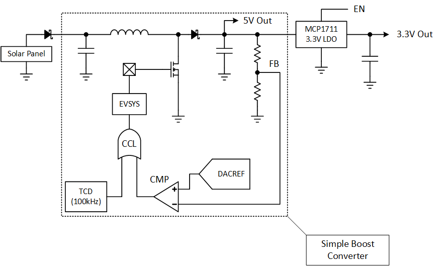
So this ~~buck~~ boost-converter is 100% core-independent. The Analog Comparator, TimerD, CCL, and Event-System are all active while the AVR DB sleeps, meaning that the microcontroller can run this simple ~~buck~~ boost-converter without any cost to CPU time.

An incredible design that demonstrates the flexibility of AVR DB's combined peripherals.

8
28
submitted 3 months ago by [email protected] to c/[email protected]

Hacker News discussion here: https://news.ycombinator.com/item?id=40560300

9
24
submitted 3 months ago by [email protected] to c/[email protected]
10
6
submitted 3 months ago* (last edited 3 months ago) by [email protected] to c/[email protected]

A random article talking about I2C on the NuttX RTOS.

I haven't heard of NuttX before, but the supported platforms (https://nuttx.apache.org/docs/latest/platforms/index.html) is quite impressive, including several chips I'm interested in. There's a number of 8-bit processors (albeit larger ones) on the list, though I'd assume this NuttX OS is best served on a microprocessor??

11
16
submitted 4 months ago by [email protected] to c/[email protected]

Edited the "I" for less confusion. The blogpost's title is "I made a...", but "I" (Dragontamer) didn't do this. I just found this blogpost and though it was relevant for this sublemmy.

12
0
submitted 5 months ago by [email protected] to c/[email protected]

I don't care what's it gonna take. I just want a connection. I guess I can connect the VCC to another voltage source, but I have the same thing happened to TX on another circuit board, although that one can "flip" (it is still attached marginally... at one end).

Board: T Deck Lilygo.

13
7
submitted 5 months ago by [email protected] to c/[email protected]
14
14
Radios, how do they work? (lcamtuf.substack.com)
submitted 5 months ago by [email protected] to c/[email protected]
15
26
submitted 5 months ago by [email protected] to c/[email protected]

Some poor sap made a few hundred DIP chip labels for breadboarding that are designed for a little more functionality than is typical. They were uploaded to github along with a GIMP file, templates, instructions, and ready to print PDF files for labels and popular kits/projects like Ben Eater's breadboard computer and 6502 projects.

The labels are intended to be more intuitive and informative than just pin labels, and these were made with brute force without programmic efficiency. For instance, many logic chips have truth tables and more. These take a lot of confusion out of the back and forth of documentation and wiring.

https://github.com/Upcycle-Electronics/ChipLabels

16
8
submitted 6 months ago by [email protected] to c/[email protected]

This PDF talks about blue and infrared LEDs + photodiode and how to create a smoke detector out of them.

The gist is to send a signal over blue LED + infrared LED, and then measure from the photodiode to see how much the light reflects back (which will only reflect back in the presence of smoke).

This design uses the 2x free OpAmps on the MSPM0L (Cortex M0+) microcontroller, showing a mixed-signal design where one mixed-signal microcontroller can reduce the number of parts.

17
11
submitted 7 months ago by [email protected] to c/[email protected]

Pretty basic but I've been enjoying Vik's articles on RF topics.

18
10
submitted 7 months ago by [email protected] to c/[email protected]

Hello everyone, I need some advice.

I am making custom PCBs for a project of mine. It's basically for a little remotely controlled robot using little DC motors. I chose the Seeed Studio XIAO ESP32C3 as the uC since it has inbuilt wifi/bt, 3.3V regulator that I can use to power the motors (can source up to 700mA) and lipo charging management (the robots will run on battery). As you can see from here, the microcontroller is surface mounted and the pads for the battery are on the bottom layer. Same story goes for the thermal pad of the microcontroller and the thermal pad of the motor driver (datasheet). I have worked with SMD components in the past and can solder them by hand, but I have never worked with SMD components that have thermal pads on the bottom layer. My question is: how to manage (route?) them? My PCB is 2-layer and I was planning on having both layers filled with a ground plane. Do I just connect thermal pads to the ground plane and call it a day? Wouldn't that make the components hard to solder with hot air? Do I make an isolated polygon that only acts as a thermal pad?

Speaking of soldering is even hot air the way to go in this case? My PCB has components on both sides, and I was planning on ordering stencils together with the boards and using solder paste, placing the components and then using hot air to solder the components in place. I thought a hot plate would be better but I don't have access to one and I don't know how that works with components on both sides.

I attached some photos of the PCB in Kicad, and here's the git repo. If it is of any help, I'm planning of having them manifactured by JLCPCB. It is also my first time using KiCad, so go easy on me :)

Thanks!

19
5
submitted 7 months ago by [email protected] to c/[email protected]

I found a radio from 2003 that was missing a power cord, and I first thought it needed a polarized C7 power cord, but it won't fit at all. Looking at it more closely, it looks like a polarized C2 connector, but it's also locking? I tried searching online but I couldn't find anything for the C1/C2 connectors that's polarized, not even considering the locking aspect. Is this something anyone is familiar with? It's not a high end or particularly old radio or anything.

Here is a link to a picture, I wasn't able to upload it to lemmy directly.

20
13
submitted 7 months ago by [email protected] to c/[email protected]
21
15
submitted 7 months ago by [email protected] to c/[email protected]

I own a Samsung monitor, and when it's in standby mode the LED blinks all night. My hearing is so sensitive, and my room so quiet, that I can actually hear the LED powering on and off.

So, every night I power it off manually. Sometimes I forget as I turn my PC off, and as I'm laying comfortably in bed, falling asleep, I hear it cycling, so I have to get out of bed, walk over, and turn it off, which delays my sleep.

At this point I'm tempted to take off the bottom panel and break the LED with a screwdriver, but I'm worried that this might change how the current flows through the monitor's circuit board.

I would appreciate any advice, suggestions or insights, thanks in advance!

22
3
submitted 8 months ago by [email protected] to c/[email protected]
23
10
What's cool about WiFi 7 (www.viksnewsletter.com)
submitted 8 months ago by [email protected] to c/[email protected]

For those EEs interested in Wireless Communications like myself. Coming from more cellular communications type of stuff, I find the fact that 4096 QAM is possible over the air crazy.

24
19
submitted 8 months ago by [email protected] to c/[email protected]

This is from a module I'm using and I don't understand this part of it. https://files.waveshare.com/upload/3/3c/RP2040-Touch-LCD-1.28.pdf

25
9
submitted 8 months ago by [email protected] to c/[email protected]

This post demonstrates a microcontroller bit-banging an old version of Bluetooth LE

view more: next ›

Electrical and Computer Engineering

826 readers
2 users here now

Electrical and computer engineering (ECE) community, for professionals and learners. Discuss ECE related topics here, for instance digital design, signal processing, circuit analysis, electromagnetics, microelectronics, power electronics, RF electronics, etc.

founded 1 year ago
MODERATORS