diy
21641 readers
1 users here now
Finally, a comm for that one user who hand-makes longbows. This ones for you, comrade.
founded 4 years ago
MODERATORS
1
81
Hi! I'm working on a DIY electrolysis hair removal solution that addresses the issues of existing options.
(hexbear.net)
Hi! Did you bump into this post from the pin on [email protected]? Check on my current progress on my user posts! This account is a dedicated alt for this project alone, sorting by my new posts will show the latest on this project.
Hey 🥰 I'm a transfem who's been working on something that I think might be of interest here and I'd love to share, because I believe that we can share a very mutually beneficial relationship. This post is about permanent hair removal.
I am going to use the term "transfeminine" in the following as an abridged version of "transfeminine, non-binary, and any other individual, queer or not, who would feel more confident and affirmed with less facial or body hair". This is a project for everyone.
A little bit of background on permanent hair removal:
Really, the only two options on the table are laser/IPL and electrolysis. Speaking to the former first, laser/IPL is without a doubt the most accessible of the two options, but it comes with a lot of drawbacks. For one, laser/IPL is neither permanent nor complete. This may sound like an immediate dealbreaker, but the ability to delay and diminish hair growth down to light wisps for months to years at the cost of only a handful of sessions makes it a valuable instrument in transfeminine gender affirming hair removal. The drawbacks don't end there though; another serious and deeply unfortunate drawback of laser and IPL hair removal is that they don't work on all skin tones and hair colors. The mechanism of action depends on light passing through the skin and being absorbed by hair roots (which then heats up the follicle, damaging it, hopefully, to the point that it is unable to continue growing), meaning both light skin and dark hair are requirements for eligibility. This is deeply unfortunate for all but People of Pasta.  There are other drawbacks, like an increased incidence of adverse skin reactions relative to electrolysis, but the two issues noted above make it a non-starter for black and brown folks and extra-bleached-flour crackers. These issues in mind, laser/IPL is a tool that can be relied on at times, but for trans folks, laser/IPL is a non-starter for bottom surgery preparation due to the incompleteness and temporary nature of the procedure.
Electrolysis is permanent, 100% complete, works on all skin tones and hair colors, and has a lower incidence of skin-related side effects. Perfect! What's the catch? Electrolysis is expensive as fuck. Where a complete course of bikini area laser or IPL may cost hundreds of dollars, the same area with electrolysis will cost thousands, sometimes as high as tens of thousands of dollars, due to the fact that unlike laser/IPL, which takes a second per exposure and can be done in areas of hundreds of hairs at a time, electrolysis must be done hair by hair, which is a lot of time to spend with a licensed cosmetologist/electrologist. Costs are similarly prohibitive for facial electrolysis, and even more wildly exorbitant for body hair removal due to the large surface area, so much that it is virtually never even discussed as an option for this. This won't do either. What is to be done? 
The mechanism of action of electrolysis hair removal is to insert an electrode in the form of a fine needle down the hair shaft and pass a current through the electrode, into the hair root, and out through a return electrode elsewhere in the body. This causes an electrochemical reaction in the hair root that produces a few nano/microliters of lye, which super, definitely, for sure kills the hair. (if you know the difference between galvanic, blend, and thermolysis, you're way ahead of the class, good eye but I'll bring it up again later.)
At home electrolysis exists, but it is not easy or cheap as it currently stands. Issues with machine quality, battery consumption, and power make this an option, but an undesirable one. My hope is that we can make it easier, cheaper, and safer, by designing an option that is more robust, more available, eats through fewer batteries, operates with greater power, and is designed with constant dynamic community dialog.
One thing I didn't lose in my transition is my audacity: surely I can make a device that applies a small current through a fine needle-like electrode in a short burst, right? So I got to researching. Can I buy professional-quality electrolysis needles without a cosmetology license? (yes, I can!) Are there readily accessible schematics for precision low-amperage current sources widely available? (yes, there are!) Are there resources available not paywalled behind cosmetology/electrology programs to learn to use this thing once I have a prototype? (yes, there are!) Has anyone tried to do this before? (Yes!!! Twice!!! More than that! Reddit user /u/abbxrdy, Github user ivanbarayev, the folks on the Hairtell forms, and Andrea James at Transgender Map, I have so much love in my heart for you. Here's to hoping that your work forms the foundation to bring accessible hair removal to all.)
My goal is to make a highly buttoned up, safe, accessible, and presentable electrolysis solution for transfeminine people to use on themselves, each other and for others to use on them. I want to cut out the cosmetologists, or specifically those in the electrolysis chain that take the surplus value from transfeminine people, like salon owners and machine manufacturers. I also want to avoid reliance on sparsely available, weak, and poor quality machines, which are the current sole option for at-home electrolysis. Ultimately, the goal is to bring safe, highly effective, and accessible electrolysis hair removal to all. Currently existing solutions generally fail on at least one of these. My objectives are as follows:
- Develop a circuit that can administer a 0.1 to 10 second pulse of current between 0 and 2 mA at a voltage between 0 and 25 V through an electrode upon each press of a button, foot pedal, or even bite switch, with no wall plug-in for safety reasons - battery power only.
- Make it into a printed circuit board that can be ordered and built out with no more than a soldering iron and YouTube tutorial level soldering skills.
- Develop a design for a probe that can hold an electrolysis needle, that can be actualized at home, without any advanced tools.
- Create a high quality and easy to follow manual for the build and usage of the device. This is missing with all current DIY solutions. This has to be something that is truly accessible to all - no electronics knowledge, wiring, debugging, multimeters, or anything else like that necessary.
- We're shooting for a budget under $100, but in general, cost is a deciding factor. It's not accessible if it's expensive.
- For now, my intention is to start with a galvanic only electrolysis machine. Blend and thermolysis produce much faster results, but I don't feel as confident working in high frequency electronics, and with galvanic being the most reliable option, despite being slower, it's the obvious pick for the 1.0 version. If this takes off, the plan is to continue with a blend or a mode-selectable version, which would really democratize electrolysis. If this works, blend electrolysis provides ten times faster hair kill time, and it's next on the menu. 👀
Here's what I'm capable of doing by myself:
- I'm an experienced multidisciplinary engineer. I have the skills to see through a basic version of this project to completion.
- I can also write a nice assembly and usage guide, I have experience in guide and technical writing for laypeople.
- I can bankroll all R&D and prototyping.
Here's what I would definitely benefit from community help on:
- I work terribly alone. I find it hard to get motivated if I don't have a team to share the work with or at least bounce ideas off of. I'm also not deeply experienced in this, and community collaboration will get rid of a lot of stumbling blocks that are probably easy avoidable. If you're experienced in analog electronics, you're the number one type of person I'm looking for, but I'd also love to work with digital/embedded folks when it comes to interface/UX time, or additionally anyone with electromechanical design experience for the probe.
- Saving the above, I still do much better with folks on the sidelines cheering me on, asking me questions, and keeping me accountable than I do alone, even if I'm working by myself.
- If you're a professional electrologist, I'd love to know what you like and don't like in a machine, what features are mandatory, what features are nice to have, and what features are pretty useless. If you have any other tips and advice, let me know!
- If you've tried DIY electrolysis before, please tell me how it went and how I can do better than whatever your most recent attempt was!
- I need help discussing the licensing. Do I want to go hardline GPL to prevent this from being picked up by manufacturers? Do I make it as open as possible with the hopes that someone can fabricate nice ones? Do I allow for manufacture with the provision that royalties be paid to some entity, which can then be redirected to some mutual aid project/charity/Maoist insurgents? Maybe even use a personal use only clause so I reserve the option to sell units as a worker's cooperative? This is all cart before the horse shit, but it's stuff that needs to get worked out before I make a github.
- What do I call it???
Going forward, I plan to post regular bi-weekly updates to keep this alive, days of the week pending Maybe Thursday and Sunday?. Look forward to the first journal entry/post tonight where I show off what I have so far! I think /c/diy is the most applicable place to post due to the comm purpose, but this initial post is getting cross-posted to /c/traaaaaaannnnnnnnnns due to the relevance in that community.
Let's stay in touch! This is an alt but I'll be checking it frequently. Thanks for being an awesome online community and I hope this can happen in a way that results in material good for my comrades. 
2
3
4
5
45
Sphynx electrolysis development journal entry #5: the most annoying bug ever; also a website
(hexbear.net)
Hey friends 
this week has been rough for this project, not gonna lie, I have a killer bug that I haven't solved yet (that I will likely solve as soon as I write all this out complaining about it, lmao) so I'm a little behind where I wanted to be. I also have a little bit of scope creep coming for me. Not a great week, but there was progress nonetheless. At least the good news is that there's no discernable hair regrowth in the one small area that I tested - it's only been a week or two, but it's reason for optimism!
What I've been up to
Last time we spoke, I said I was gonna be designing and ordering the Lite Alpha 1. Sadly, I'm not there yet. I did implement fixes for all of the bugs mentioned in the previous post into the start of a Lite Alpha 1 schematic. Unfortunately, a lot of that was low hanging fruit. I have two more daunting challenges ahead of me before I can order boards and actually make a Lite Alpha 1. The first, which is really deeply killing me right now, is a bug, the second is a feature that I'm kind of deciding is necessary that I'll mention in new developments.
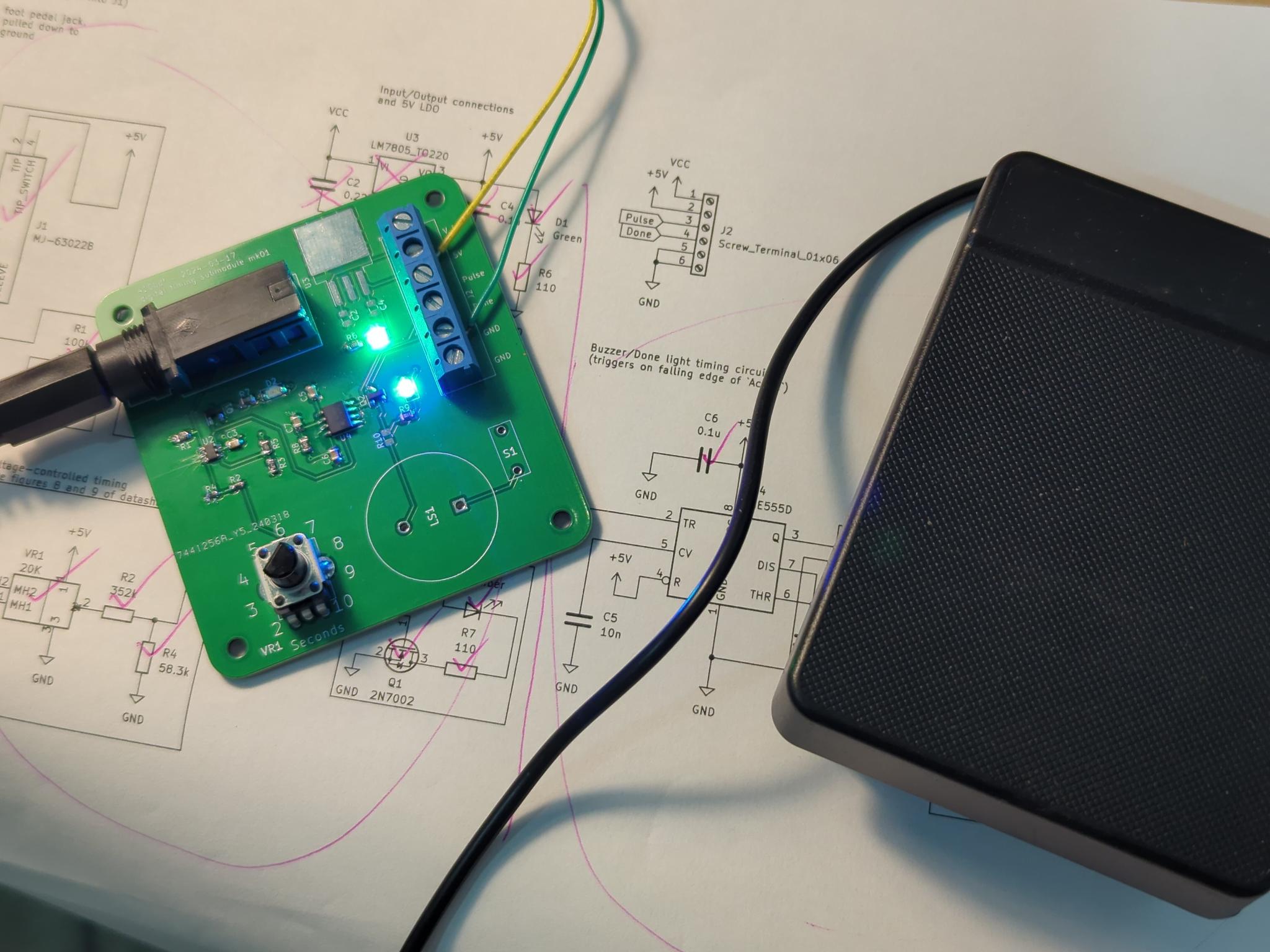
I wired the two boards from last time together to test as one unit, here's what it looks like:

Here's the bug behavior:
- Power on the board, everything looks OK. Active light off, done/ready light on.
- Put the probe in a follicle. No current draw.
- Push the pedal. Active light on, done light off, current comes from the probe. Good!
- Timer finishes, active light goes off, done light comes on, current doesn't stop flowing. Bad. Even after removing and reinserting the probe, current starts flowing again. Until you power cycle the board.
- On paper, this sounds whack but very possible to debug, but crazily enough, I can't reproduce it with a 10K resistor instead of my body.
Next paragraph is kind of jargon-y word barf that I didn't bother to make explicit or clear or referenced to the design, sorry in advance, I partly just needed to complain, but: I'm worried it has something to do with the fact that the return line of the probe is technically not ground and instead a current sink floating just a little above ground. If that's an issue, then I need to idunno make a negative supply or something and I really really don't wanna. It could be a thousand other things too. My only big lead is that if I physically disconnect the Pulse line with that switch you see in the photo, it doesn't sink current any more, so it's probably something wrong with the digital timing board. The voltage appears to be 0 even with it connected, the light is off, and it's even tied down via the potentiometer on the current source board, not to mention the LTC6993 says it can sink current through the OUT pin so even if there is something driving it high it should get pulled low. The mechanism of action here is that the potentiometer that divides the voltage that goes into the current source input is driven directly by the pulse line. I'm completely lost. It doesn't help that I'm doing this all with nothing but a single multimeter to debug. I think I'm going to buy an oscilloscope for this. I've wanted one for like a decade now and this is as good of a reason as any. It delays things, but hopefully this will speed up all testing I do from here on out forever.
Oh, and I caught and fixed another easy bug - I noticed that every time I turned off my soldering iron, the board would trigger. Luckily I knew right away that that's a noise thing. I added a 1 uF capacitor filtering the pedal line to ground and I don't get false triggers any more. Cleaner pedal signal, one less source of false triggers. yay 
New Developments
I've decided that if I go ahead with the design as it is now, operation will kind of be firing blind. The user has no way of knowing how much current or voltage is coming out. I really want to keep the Lite simple, but I don't think it's acceptable for the user to not know if current was even getting delivered through the hair follicle. So I think it's in order to add one more part to the design before making an Alpha to debug and iterate on. Basically, what I want to do is make a status light that goes on if you are delivering >90% (arbitrary and subject to change) of the current that the knob is actually set to so that the user can know if the device is working with each pulse. I'm lucky I put that current feedback instrumentation amplifier in the last design, I had a hunch it would be useful and now it is: all I need to do is compare the voltage on the input of the high-side current source with the measured current times some factor, probably done with another instrumentation amplifier on the middle leg of the potentiometer on the current sense board. If the current feedback is 90% or higher of where the set voltage has it set to be, the light comes on. It adds a few parts and some complexity, but in testing, I was finding that moving around, having a bad insertion, or any number of other things could make the current drop and deliver an incomplete hair kill, and without a light or an ammeter hooked up, the user has no way of knowing whether each pulse works, and an entire session could turn into wasted time. I hate to make things more complicated when I'm already having problems, but I think this one is necessary. 
Outside of electronics, last time, @[email protected] mentioned that sourcehut has a site hosting feature - thank you lilypad! You're so right and I set it up and put up a splash screen and I think this is a good solution! She also mentioned that printable manuals are probably a good idea - I 100% agree, my thoughts for this were to ensure that whatever site generator we use, should we make our own theme, we make sure that it's print-optimized. Static site generators usually have Markdown-based pages and that's also compatible with Pandoc, so it'll probably be pretty doable to get them over to LaTeX too for that beautiful, beautiful formatting. Good looking out 
@[email protected] also did a lot of good thinking about static site options in the comments last time - thank you as well  probably gonna link its post down below in the comments when we talk about how to make a site!
Also - shout-out to @[email protected] for their amazing work figuring out a probe design in the comments of the last post! I haven't started building one out myself yet but I have some of the parts on the way in the mail and it looks like their work will probably be the basis for a needle holder probe, something that's necessary before we can fully release a Lite. Thank you bestie 
Next up
Obviously I need to fix my bug and implement my feature. Besides that, there's not much else to mention in electronics. It's still too early for enclosure stuff, and the electrical design is too much of a moving target to start trying to port to JLCPCB, so I just have to fight through this one. All other new developments outside of me bashing my head against these two new problems will be in both the site and the applicator probe.
Any ways to help?
I think it's time I opened up site development to interested parties? We're not in a rush but it's on the table! If anyone wants to mess with Jekyll/Hugo/something else and sourcehut's build system, I set up a repo to connect to it, so with the right configuration, we can have a build job generate with Jekyll or Hugo or something and automatically deploy. That's here: https://git.sr.ht/~_410bdf/sphynx-site I'll make a top level comment to aggregate people who want to work on that below! We can work out what static site generator we want to use together and then we can start getting it set up!
Also, 100% looking for ideas on things to test on my bug, if you're good at electronics debugging, throwing some test ideas at me would be greatly appreciated.
As always, stop by, hang out, say hi, ask questions, tell me what you've been up to, design review me, however you'd like to be involved is good by me! All the love and look out for my next post in a week or so!
6
7
Hello, comrades! I'm mostly not sick any more! Sorry so much for the week plus since my last post, most of the time I spent in that timespan was doing other things while I waited for components to arrive (especially because there's stuff I forgot in the first order and had to make a second one  ). Components got here, I put everything together, and things... work more than they don't work
What I've been up to
Behold:

The boards are in and I made them and they work
This segment of the post is going to be dense and technical, so feel free to skim and ask questions if you feel lost and want to get caught up!
Both boards have minor bugs that I will be addressing in the next revision - the next revision being the Alpha 1 version of the Sphynx Lite. The bugs I have are as follows:
Current pump bugs:
- The knob is wired backwards. fix: make the knob go forwards, or more specifically, switch pins 1 and 3 on VR1. Ez.
- The knob doesn't have a zero offset - instead of 0.1 mA to 2 mA, it goes 0 mA to 2 mA. This is annoying; if you turn the knob all the way, the device won't do anything, you have to bump it a tiny bit. The solution is to put a resistor of roughly ~~11~~ ~~5.5~~ 1 kiloohms on the low-side leg of the potentiometer (exercise for the electronics-curious reader to figure out why! check the schematic from my previous post!). The wide tolerance on the potentiometer means there will be somewhat of a range on the actual minimum current, but it should be a pretty small variation, around 0.08 mA to 0.12 mA worst case variation. Since this error 1) gets stacked up with the error of the user's body being different from everyone else's, and 2) is only error on the low side, not on the high side, I'm deeming it tolerable.
- Not a circuit bug per se, but I designed this around a INA350CDS, which has 50 times gain, and then I accidentally bought some INA350ABSes, which only have 20 times gain. This part is a new addition that uses R1 as a shunt for active current measurement. It works exactly as intended, just with 20 gain instead of 50 gain. This can be used for a lot of things, but particularly, an automatic shutoff of the board if the current draw ever goes above, say, 2.5 mA. More safety! However, this component has another problem, which is...
- The INA350 is fucking impossible to solder
 All these new space saving packages are absolute nightmares for hand assembly. I didn't even need space savings, it was just a cheap instrumentation amplifier that worked nice. I think I might have to ditch it because it doesn't come in a usable size. The same thing can be done with a dual opamp and some bonus resistors, which is less than $0.50 and I already have them on the board.
Digital timing bugs:
- Backwards knob again...
- Ignoring backwards knob, the range, instead of being 2 seconds to 10 seconds like I expected, is actually 2 to 7.5ish seconds. I haven't actually figured out why on this yet - I think it's because of the relatively simpler resistor divider thing I did with R2/R4/VR1, and there's some other current path I haven't thought about yet through the potentiometer. Could be something else too. In any case, the move here is probably to do something more like in figures 8 and 9 of the LTC6993 datasheet with an opamp current sink and a potentiometer, and something less like what I did, which came from the unlabeled figure on the last page of the LTC6993 datasheet. Again, one more part, but opamps are pennies and I use them elsewhere, which drives the cost down further.
- The LTC6993 is one of the microtiny packages too. This is a little worse than the other microtiny package in the INA350, in that I can just buy another inamp or an opamp for that one, but the LTC6993 is fairly unique and I can't just shop for another part that does the same thing. I'm not sure what to do about this. It's too late to add a microcontroller, but this timing issue just won't let up. I think the difficulty to solder this one might just be a thing to fix in the Lite 2. Technically, you need this level of coordination and fine motor skills to do the actual electrolysis hair removal anyways, and I was able to do it with nothing but an iron, a solder sucker, and a magnifying glass, so it's not impossible and anyone with even slightly better tools than me should be okay, but it's still a bummer. From now on, new rule, nothing smaller than a DFP package. If I get rid of the INA350 and this, then there's no more.
- The done alert doesn't work. The intention was that LED D3 turns on and buzzer LS1 beeps for half a second when the current pulse is done, alerting the operator that it's time to move to the next hair. This circuit is everything connected to U4 in the schematic in my last post. Not only did I pick the wrong kind of buzzer (very easy fix I just need to shop better), but the whole timer sticks on forever instead of just flashing on for half a second. I didn't know this at the time, but if I were to read the damn datasheet, I would have seen on page 10 that: "Monostable operation is initiated when TRIG voltage falls below the trigger threshold. Once initiated, the sequence ends only if TRIG is high for at least 10 μs before the end of the timing interval." Basically, the 555 wants to see a super quick off/on to start the timer, and I'm just giving it an off with an indefinite delay after, causing the timer to stick on. I don't really know how I'm going to handle this to be honest - my current best guess is to make some kind of quick and cheap RC high pass filter thing hooked up to a transistor that turns a high to low edge into a high to low to high pulse. I'll have to breadboard or simulate it a little bit, but if I can make this work it's a very cheap fix to the problem.
I'll be fixing this list of issues and moving both circuits to a new united design with test points and jumpers this time (thank you @[email protected] ) that will be, if it works, the first alpha version of the Lite. Progress!
I also cleaned up git - not sure if anyone has tried to pull down the repository and look at the boards yet, but if you have, it was broken - it should be fixed now, but you'll probably need to re-clone. If anyone tries this, let me know how it works!
New Developments
I bought a domain name! Meet sphynx.diy
Currently empty, just points to the git repo, but you have to start somewhere - this is where I want to host blog posts like this one, the assembly guide, and the usage guide and resources in the future. I'm not going to be doing much with it immediately myself, but having this makes it so we can start working on an actual site! I was thinking GitHub pages for hosting with a cute Jekyll theme, or maybe readthedocs like mentioned last time - thoughts?
Also! I used the boards above to remove a couple square centimeters of hair as a proof of concept! It's only been a couple days but I'm optimistic - I tested by tugging on the hair with tweezers, observing it tightly connected to me by the follicle, applying about 10 units of lye per Figure 2 of this very helpful resource I found, and then after current application, pulling again, for the hair to slide out with no resistance, which is a very strong indicator that it worked! Stay posted to see if they stay gone or if I need more juice, 10 units of lye is on the very low side but I'm playing it safe.
Next up
I'll absolutely be fixing up the boards as mentioned above and making and designing an Lite Alpha 1.0 next! I don't want to suggest that this one be used on human beings, but once I make it, it might be fun to buy and assemble for research purposes? Probably not, maybe best to wait until I at least make it to a beta version, but in any case I'm excited for it! It's also not too early to get work on a manual started - this is something that I'm going to try to lean on community help for.
I'm also exploring JLCPCB assembly - it would be much better for accessibility if I could keep 100% to their parts catalog (plus I wouldn't feel bad about using microtiny packages any more), and for now I think I'm close, but I know that there's at least a potentiometer I use that isn't in their catalog.
Any ways to help?
There are starting to be more things to do! I'm kinda feeling like it might be time to start pulling in folks for web stuff! If anyone has GitHub sites or Jekyll experience, getting going on a place to host an assembly guide would be awesome! This is also something that should be doable even without this particular experience if you know web stuff, so don't feel intimidated - I think this is accessible with a bit of new learning for anyone with intermediate web knowledge.
Another thing I could totally use help with is BOM management - I have links for all the parts, but I don't have them linked anywhere and I don't have them automated, tallied up based on cost, in a convenient one click buy cart, or anything else like that - if anyone likes making bills of materials in KiCAD, let me know, that would be super helpful! In a similar vein, having an audit and maybe a port of my design to 100% JLCPCB catalog compliance would be extremely nice, if either of those things sound interesting to you, let me know!
As always, stop by, hang out, say hi, ask questions, tell me what you've been up to, design review me, however you'd like to be involved is good by me! All the love and I'll talk to you in a week or so!
8
9
39
Sphynx electrolysis development journal entry #3: More boards, more safety, and we're on sourcehut 🎉
(hexbear.net)
Hi friends - still sick, feel like ass, but I did a lot of work recently, and if everything goes according to plan, within 2 more journal entries, I'll be able to report on my very first hair removal test!
What I've been up to
This week was mostly board and circuit design. I just ordered two more circuit boards I designed, here they are:
Current pump, mk2
Schematic:

PCB:

3D PCB:

I talked about this one in Journal Entry #1 - since then, I received the board and the parts for mk1, and it works 
Technically, this means I can test hair removal on myself, but I'm going to try and wait until I have the new board, for a lot of reasons. Here's what I changed:
- Before, the current went out a current pump and went in to ground. If the current pump were to malfunction, it would cause more current than expected to leave the probe, which is a safety issue (not electrocution level, but possibly a scarring issue - very bad). I added a current sink hard-wired to 2 mA on the return of the current probe so that even if the current pump fails, the current sink will still cap the max current at 2 mA.
- I added feedback so that I can measure the output current from a microcontroller. This is pre-work for the Sphynx Uno, and it can also be used as a safety measure - if the current goes too high, I can cut board power and flash an angry red LED as an error light.
- I added a current knob! This is one more thing to test for the final version.
- I broke out and very neatly labeled parts of the schematic so that this is an easier resource to learn from as an outsider.
- I changed up some resistor values to make the current pump and current sink more stable.
My highly scientific outlook on this one is that there's a 75% chance it works as intended first shot.
This is the board I'm going to use to test hair removal on myself (if it works)! If it works, there aren't really any other current pump related changes to make and this one can get incorporated into the Sphynx Lite!
Digital timing, mk1
Schematic:

PCB:

3D PCB:

@[email protected] game me some really good feedback on this one in Journal Entry #2. I since figured out a better way to make the timer work by actually reading the manual for the part I'm using. This means the knob I'm using will actually be accurate and not have a dangerous failure mode! yay!
This one is a little less likely to be perfect on the first try - it is all new, unlike the current source, it's also a little more complicated, and because of that, I'm giving it 40% odds to work on the first try.
When I get these two boards, if they both work as designed, I will be able to plug in a benchtop power supply, rig up some kind of weird holder for an electrolysis needle, and go for a spot of hair on my thigh I've been growing out for this moment! Journal entry 4 will probably be me designing and ordering the battery submodule, so journal entry 5 will be my first report of actual hair removal!
New Developments
We're on git! Specifically sourcehut! https://git.sr.ht/~_410bdf/sphynx
It's somewhat empty right now, it's also especially clunky because I just set it up and all of my commits are just dumping in all of my files, but now people can actually look at my files and mess with them for themselves, or even contribute if there's anything that anyone feels comfy adding!
Next up
As mentioned above, steady progess, waiting for boards to come in, making the battery board, and probably before the end of March I'll be starting to get rid of some body hair. End of April is a very reasonable timeline for a beta version of the Sphynx Lite to be available for enthusiastic individuals to order, build, try, and review! We're getting there!
Any ways to help?
Calls are out for a Sphynx logo for sure! Design review is always appreciated as well! Besides that, I'm just working through the early stuff, things are a little too turbulent at the moment for me to ask for much because things are moving too fast. Once I'm working on the Lite, it'd be SO sick if anyone artistically inclined would want to design some cool silkscreen for the Lite, maybe with a Blahaj, some trans/commie logos, possibly some original artwork - the possibilities are endless 
This one's a little terse because I'm sick and tired, but as usual, from last time - If you have any questions, please ask below! It doesn't matter if they're technical or non-technical, it doesn't matter if you think they're basic, dumb, not worth my time, or anything else - I want people to get excited about this and I would love to take the time to communicate the inner workings of this to y'all so that everyone can be included! I can't guarantee I'll reply to everyone but I'll do my best to reply to comments that are asking something directly or I have something to add to!
10
11
55
DIY electrolysis doohickey journal entry #2: Timers, trajectory, and a real project name
(hexbear.net)
Hello! It has been a week! I did some work on this! Not as much as I'd have liked because I'm sick (I believe not COVID, it's been fairly mild and if it is COVID my vax is fresh but I'm still avoiding doing a lot).
What I've been up to
The main engineering achievement of the week was finishing drafting a schematic for the timing part of the circuit. Brief step back, in terms of development, I am breaking the first version into 3 separate pieces: the power board, the current pump frontend, and the timing board. I'm doing this so I can debug them all separately; if one of them ends up being broken and I need to wait on a new PCB or components, it doesn't block me from working on the other two. Once they all work, I will unite them all into a single PCB that will form the final version of the first release. The timing board is the most complicated of the three, and it itself breaks down further into three more parts (all on the same PCB). These are:
Power conditioning:
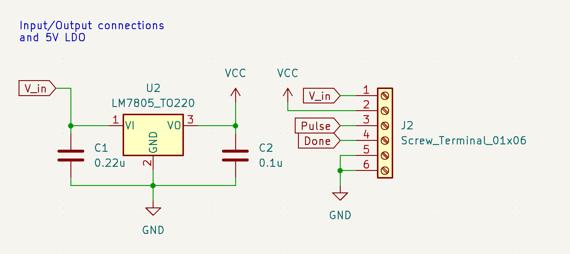
All this is is connectors to hook up inputs and outputs and a basic voltage regulator to turn the input voltage into a clean 5V to do logic circuitry with.
Pulse timing:

This is the part of the circuit that activates the current pump I drew, layed out, and ordered from my previous post. This thing has a 6.35mm jack that you plug a sustain pedal from a keyboard into (deeply proud of this idea - transfems are literally known for their audio equipment!), and on press, it will start a 5V pulse that is anywhere from 1.5 seconds to 12 seconds long, depending on the position of knob RV1. This 5V pulse will activate the current pump frontend. Notably, I am not using a 555 timer. I spent so. much. fucking. time on this fucking part of the circuit, the 555 was utimately to imprecise to feel good about including it. I was going to use a fucking crystal oscillator to keep good time at one point, and then finally I luckily found out about the LTC6993, which is an awesome 555 replacement that every amateur electronics person should get comfy with because I am never using a 555 ever again. There's still fairly sizeable error from RV1 being +/- 20% tolerance, but at least it's not stacking up from several parts, depending heavily on temperature, or any of the other problems a 555 has. This part would be a thousand times easier with a microcontroller, but at least it doesn't need to be flashed. @[email protected] you tried to warn me and I didn't listen lmao
Feedback
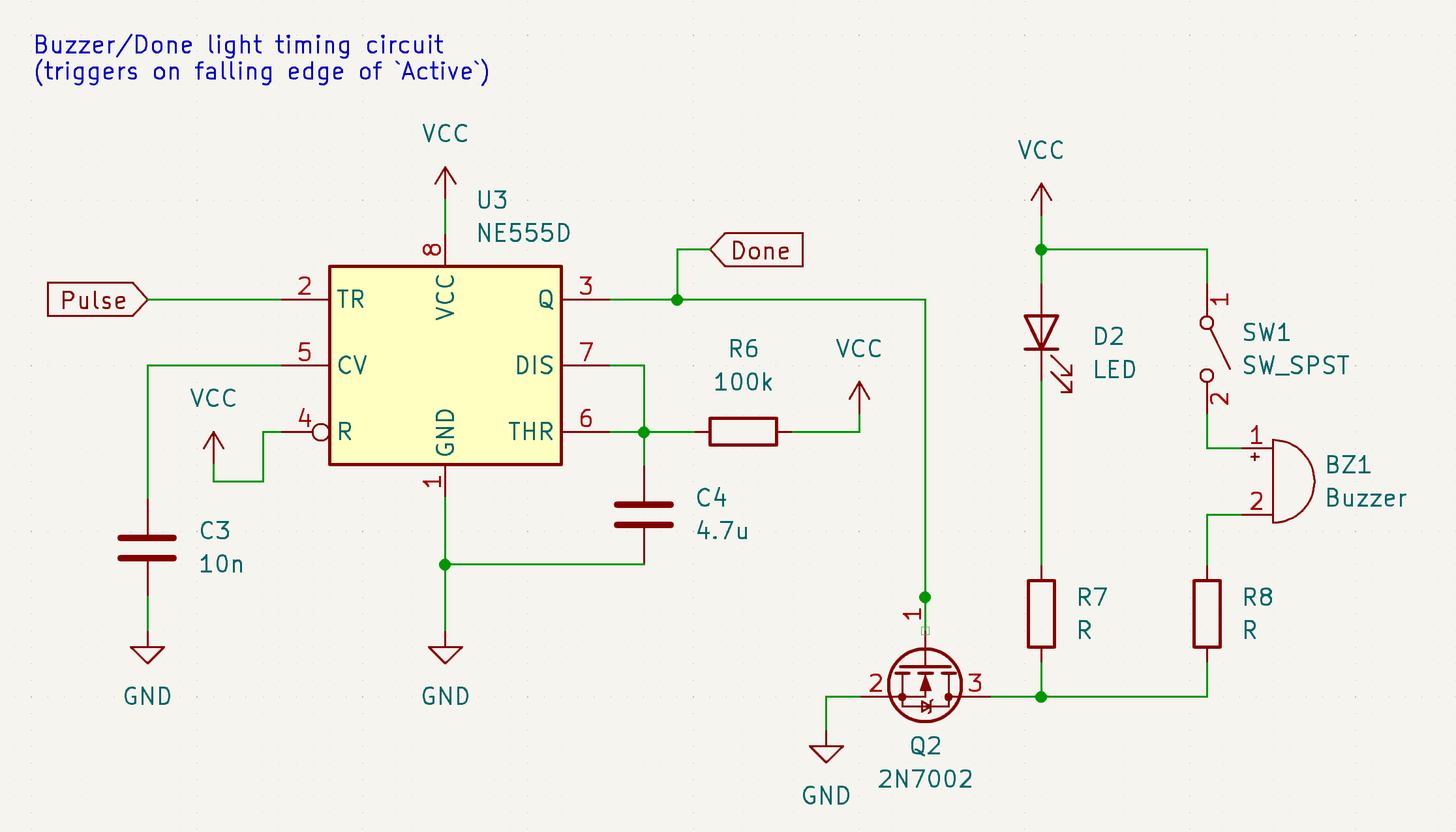
Basically, as soon as the pulse is done, this board will turn on a little "OK!" LED and, if the switch is on, make an audible beep. This one can be a 555 timer because I don't care precisely how long the beep is. Right now it's about a half a second.
These three are all on one board. I still have to identify components to use for some of these (LEDs, buzzer, switch, 6.35mm jack, maybe more?) before I can lay out an actual PCB like I did for the current pump, but that's what I have coming up next.
That's been my week! Not a bad run if I do say so myself.
New Developments
First and foremost, I made some tough choices about how I want to plan things going forwards. I have a long and often times self-conflicting priorities list, so I wanted to come up with a road map that satisfies as many of the goals of the project as possible. So, the road map going forward from my side will be as follows:
- First, I'm going to make a push to release the first iteration, the minimum viable product to providing safe, accessible, and effective electrolysis for anyone who wants to make one, with no bells and whistles. This will have a lot of cuts (full list below) but it'll be 100% sufficient to perform electrolysis with and I'll only release it when I've confirmed that it works and it's safe. I'm going to be calling this version the Sphynx Lite.
-
- From here, once the Sphynx Lite is released, things open up for contributors to do more things for the project. This is where I'd love a couple of particularly passionate and initiated folks to get involved and start doing things like writing documentation, designing enclosures, revising the circuit to release a Sphynx Lite 2, and more. Hopefully with the board and a minimal instruction manual I'll provide for its operation and making rudimentary peripherals, we can get an ecosystem going.
- Once the Sphynx Lite is out, start work on the Sphynx Uno (Sphynx Ein? just "Sphynx"? Sphynx один? still workshopping this one a lil bit) that will roll in all the nice to haves that I left out of the Lite, while keeping a lot of things I've put effort into and would like to keep, like the current pump.
-
- With the Uno, there'll be firmware - this is where community folks will really be able to shine, for one, this is the thing that the most people expressed interest in helping with, and for two, this is the thing that allows development to be distributed, people to work on multiple things at a time, and the project to really start picking up steam.
- Once the Uno is on a clear trajectory across the finish line, that's when we can start working on the final boss, the Sphynx Wave.
Rundown of the 3 models I could ever imagine intending to make:
- Sphynx Lite: Takes 2 9V batteries. No microcontroller, no screen, likely not even a 7 segment display unless there arises a good safety argument for needing visual feedback on voltage and current, just a knob for max current, a knob for max voltage, and a knob for pulse time, with a beeper and a couple LEDs for feedback, and connectors for a foot pedal activation switch and a probe. All digital and analog electronics - no flashing required.
- Sphynx Uno: Add a microcontroller, rehash a lot of things that will benefit from having a microcontroller, like timing, input method, and whatever else comes up. Replace the 2 9V batteries with a LiPo with a proper power infrastructure, including boosting, possibly to a slightly higher voltage than the Lite, USB charging, and more.
- Sphynx Wave: Everything that the Sphynx Uno is, except instead of just the DC current pump on the frontend, add an RF power applicator circuit to the output as well (this is nerd talk for "Uno is galvanic only, Wave is galvanic, blend, or thermolysis").
(thank you to @[email protected] for suggesting the Sphynx name! I think I'm gonna keep it! )
I've also decided that open hardware is probably the move licensing wise. It doesn't preclude me ever getting something together to start selling units, but it also keeps this a community project and allows anyone to build it as cheaply as they want to, remix it, or do anything else they'd like to themselves.
Next Up
The components to build and test the current pump are waiting on my bench. I have to build that, test it, and then honestly I can fake the rest with an Arduino and a benchtop power supply to test the output parameters and kill a test area of hairs if there's no bugs in my circuit and start the waiting game to see if they come back. I also have to lay out the timing submodule, and I have to both design and lay out the battery/power submodule. Once they all play nice tied together with wires on the bench, I'll dump all 3 designs in the same file and start weaving them together to make the Lite.
Any ways to help?
Audit my circuits above for sure, I'm being dumb and ordering a PCB before testing most of this on the bench. I'm going to add some more debugging features to the design before ordering the design, but still it'd be nice to catch as many mistakes as possible early. I also have an interesting request:
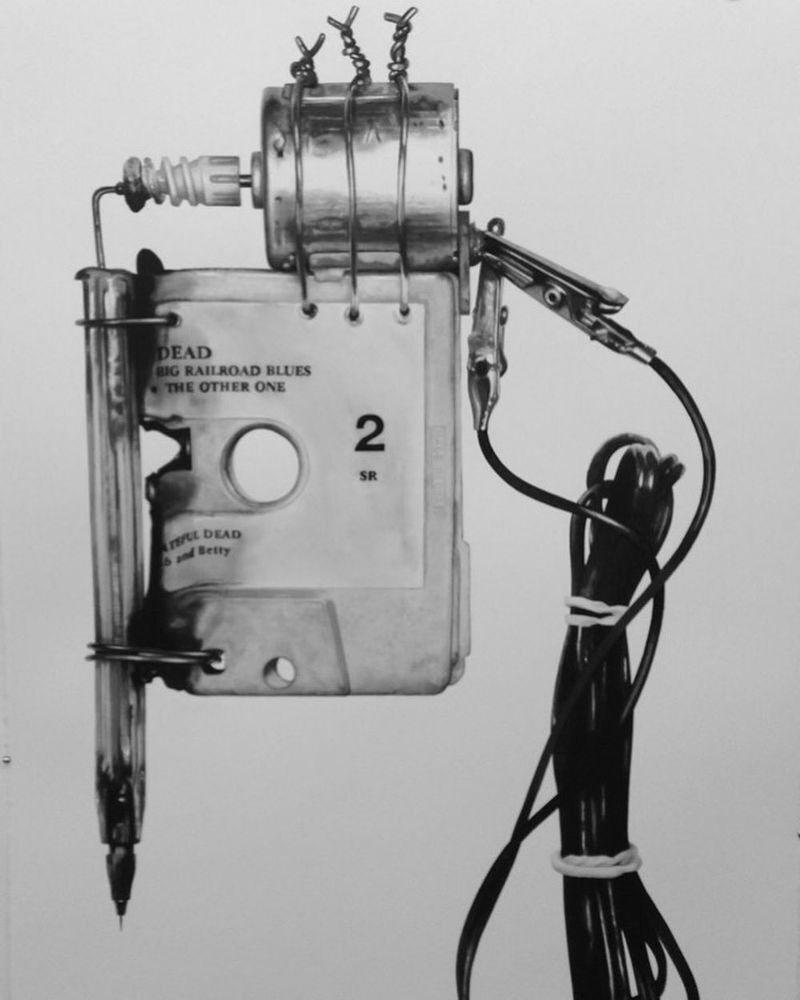
Synoptic seems to be using a modified mechanical pencil as a probe - does anyone recognize this make of mechanical pencil? I'd love to get some and see if they lend themselves well to being made into probes. I owe you all an actual drawing of what the probe should look like and do next time too, it'd be awesome if someone could figure out how to make the probe work. If anyone feels like taking a stab at it now though, ask anything you'd like to know, but in short, all it needs to do is hold onto an F-shank needle with electrical continuity in a way that is easily replaceable and can be held like a pen. Bonus points if there's some type of shroud to cover the tip when not in use, but that's not a huge deal, it's more important that this doesn't require any advanced tools - accessibility.
Now that I've committed to a name, we can start thinking of a logo too! The added bonus of using a cat is that it's extremely reasonable to incorporate a ":3" into the logo. I would love to see suggestions if anyone's bored and looking to help! My only ask is that it should have a good monocolor representation and that it doesn't have any tiny features so I can put it on the PCB itself. If you can draw it with a sharpie, it'll work perfect.
If you have any questions, please ask below! It doesn't matter if they're technical or non-technical, it doesn't matter if you think they're basic, dumb, not worth my time, or anything else - I want people to get excited about this and I would love to take the time to communicate the inner workings of this to y'all so that everyone can be included! I can't guarantee I'll reply to everyone but I'll do my best to reply to comments that are asking something directly or I have something to add to!
Tag list is in my top level comment below, reply to that comment if you want to be added or removed. Love you. Thanks for being here. I hope I can do good by my favorite internet people. :trans-heart:
12
13
Hi! As promised, here's my progress so far. This post will also be the loose format of how I want to post these in the future. I intend to have four sections: what I've been up to, what new developments have come up, and what I have planned next, and if there's any immediate opportunities to help. I also want these to be written casually so I don't have to agonize over them, and so that they're fully readable by technically experienced folks but also skimmable with occasional tl;drs for curious but not electronics literate onlookers.
What I've been up to
In ultra brief summary, my last week on this project was giving up on the LM334, which is a lovely chip if you want a precision low-amperage source (seriously I was getting stable single microamp precision), but it just has too many quirks for use as an on the fly adjustable current source. I've since committed to a dual opamp design I found on some blog somewhere and I haven't looked back, because it seems to work perfectly. I designed a circuit, simulated it, it worked swimmingly, I laid it out on a PCB, ordered it, and ordered parts to build it out.
Here's the blog post - I went with the "Two Op-Amp Topology". It's actually sick as hell. Here's my implementation of it in SPICE:
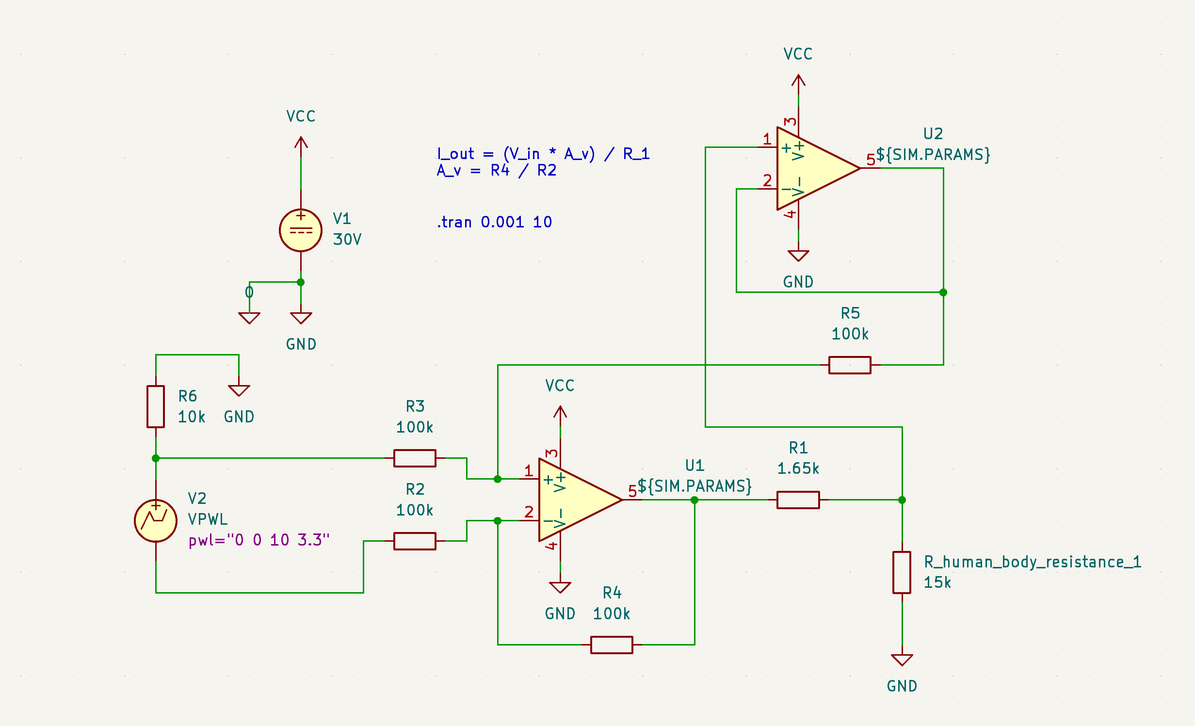
Something I'm really adamant about on in regards to safety (a core objective) is that this needs to have hard limits on both current and voltage. I've been able to design this in in the simulation, see:

It's hard to tell exactly what's going on here if you don't know how to read circuit diagrams and also know how I set this up, but essentially, I'm varying the simulated human body resistance and looking for it to behave the same way as I do so. Even if the device can drive the amps into you by current and voltage availability alone, it's hard capped at 2 mA, with the voltage limit imposed by whatever voltage you give the opamp and the current limit imposed by (basically) the resistance of R1. (More technically, this is a voltage controlled current source, and the voltage applied to V_current_set is divided by the resistance of R1 for the value of the current sourced from U1A.) All bodies are not the same resistivity, all parts of the same body are not the same resistivity, and even the same part of the same body is not always going to be the same resistivity. It's important that the administered current and voltage don't vary based on user, body part, and et cetera. This is an important safety and performance feature that most other DIYers I've seen have omitted. This is exactly what I was hoping to see this design do and it nailed it.
So, I drew up the circuit, routed the PCB, and with that, we're here:
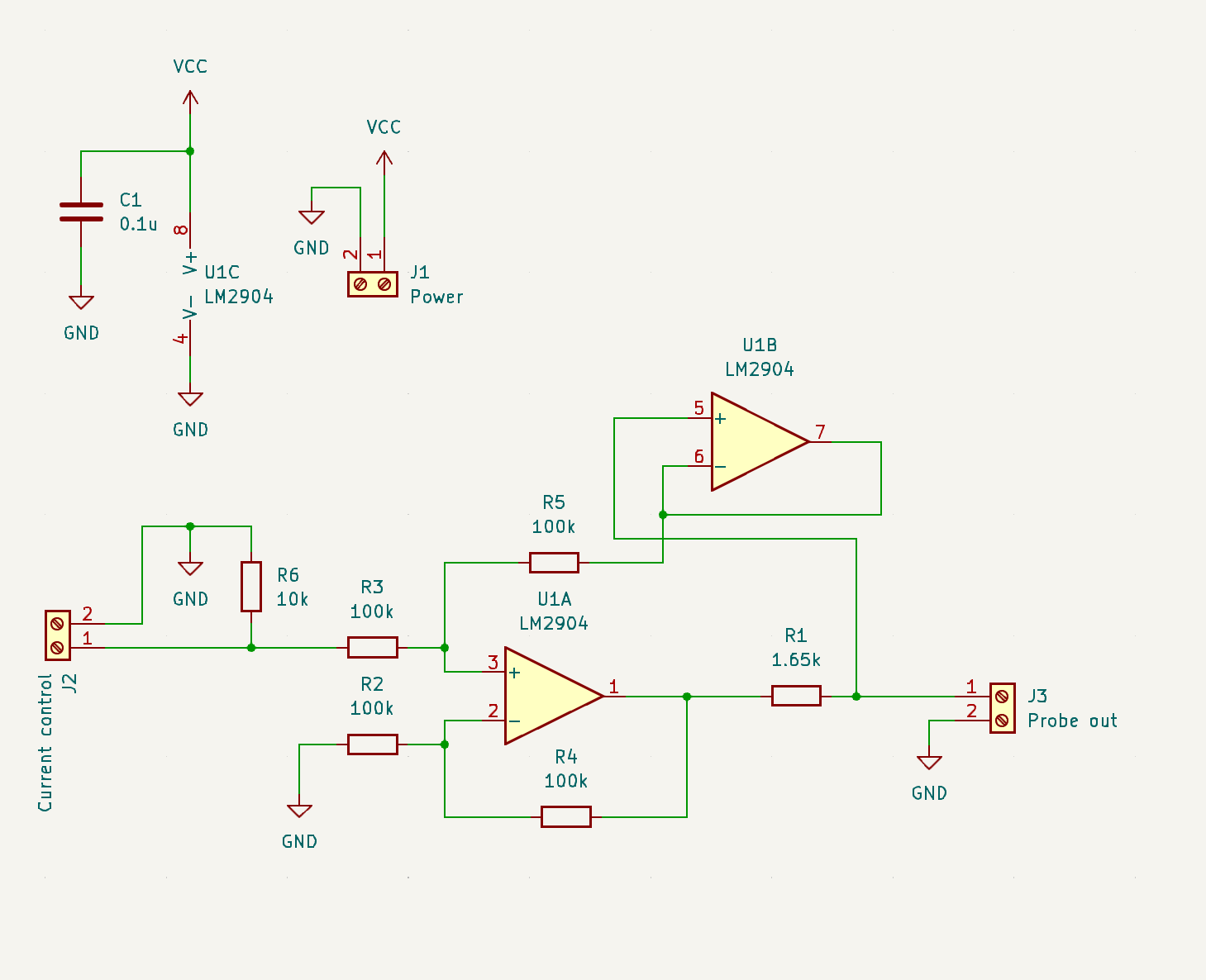
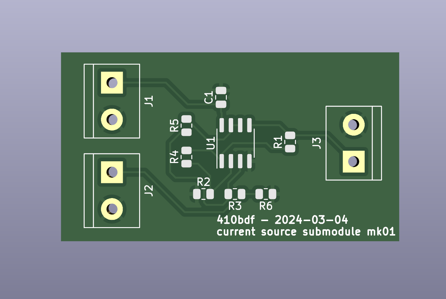
It comes in the mail next week! Thanks to @lapis and @macerated_baby_presidents for the JLCPCB rec, I didn't get a populated board, I wanna build it myself, but their service has been nice so far and I look forward to ordering a populated board from them soon to test accessibility! I left off test points, status LEDs, and some other stuff. That's okay. I'll do better next time. :comfy: The important thing is that this circuit is the circuit I'm rolling into 1.0.
Non-technical tl;dr: This is the circuit that takes in a normal power source and conditions it into the correct amount of power, specifically voltage and current, to kill hair follicles in a safe and controllable fashion.
New developments
I decided to give up on microcontrollers. 💔 For now.
Adding a microcontroller adds a lot of pros, and a lot of cons. The upshots are that it really makes this into something cool, something with flipper zero vibes - I'd be able to add a splash screen with graphics and I'd be able to explicitly list voltage/current/pulse time numbers on a display, I'd be able to shift a number of changes into firmware over hardware, meaning quicker debugging, and more. The downside though, is that I'd likely be requiring end users to flash a firmware build (not accessible, breaking one of the core 3 objectives), I'd be dealing with a data bus like SPI to get the screen to run, which is a pain to debug, and I'd be opening myself up to feature creep. I decided to axe it for now and just do everything by knobs with no screen to be able to get y'all a working basic finished project sooner. ❤️🩹
Next up
My availability is somewhat limited for the next week, but I want to at least build out this board and test it on the bench to make sure it actually applies the current I designed it to. While I'm waiting for this, I can start to design the other parts of this circuit. I have the power conditioning designed, next up I need to design the following, roughly in this order:
- instead of just loose inputs I put voltages on, I want to make knobs that set the amperage.
- I need to add timing circuitry so that instead of just an on/off, the user pushes a button and the device outputs current for an amount of time configured by a second knob.
- I need to add power conditioning, so that a 9V battery, an 18650, or something like it can be boosted up to generate the voltage required to drive the current required to smoke ur hairs.
- Fit and finish. Oh, and all of the activation switch and applicator probe everything.
I can probably design 1 and 2 in the next week. I definitely won't be able to actually build and test them until late next week, but now that I'm getting better at SPICE, I can simulate them, which will give me the (probably ill-founded) confidence to order boards without testing anything on the bench first. Likely no updates until mid next week due to this.
Any ways to help?
First of all, ask to be put on the tag list if you want updates! Knowing there are other real life human beings who think this is cool helps me a lot. Besides that, no electronics help at the moment, I don't have enough done to have any shared work to propose. Soon, I'll start thinking about the current probe, and I'll need help thinking about that. Besides that though, just get hype and if you know anyone who knows anything about electrolysis hair removal, let them know about this so they can be here for discussions if they want to be!
I'll see y'all some time next week for the next update. Thursday of next week or earlier. It's in my calendar. Bye!
tag list: @[email protected], @[email protected], @[email protected], @[email protected], let me know below if you want to be added or removed!
14
15
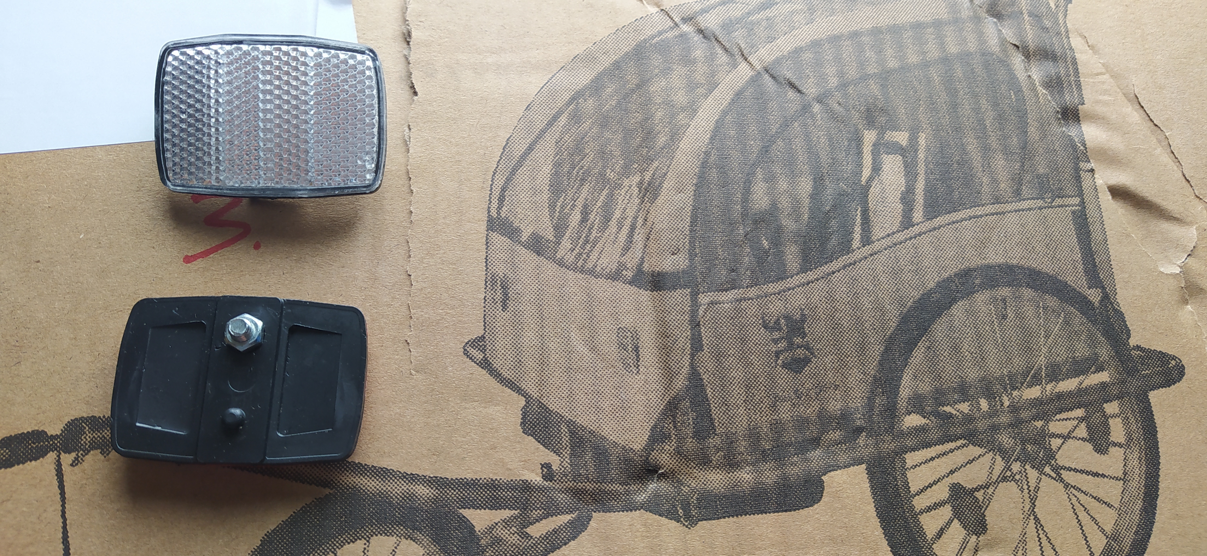
I'm assembling a bike trailer and I don't know how I'm supposed to attach the reflectors.
The instructions are in Dutch only and only seems to mention that reflectors exists but gives no instructions on how to put them on. The only directions are the grainy photo on the box, showing something that looks like reflectors being attached to the fabric of the cover.
The reflectors themselves (two white ones and two red ones) have a short screw and nut as well as a short protruding plastic pin on the back.
There are no holes or similar obvious way of attaching the reflectors. Am I literally supposed to poke holes in the fabric myself?
Edit: Jesus Christ, they literally poked two small holes in the fabric to attach the reflectors. Aren't the Dutch supposed to be good at bike stuff?
16
56
Said I might take a picture of my desk like a year ago but I always enjoy showing it off
(hexbear.net)

17
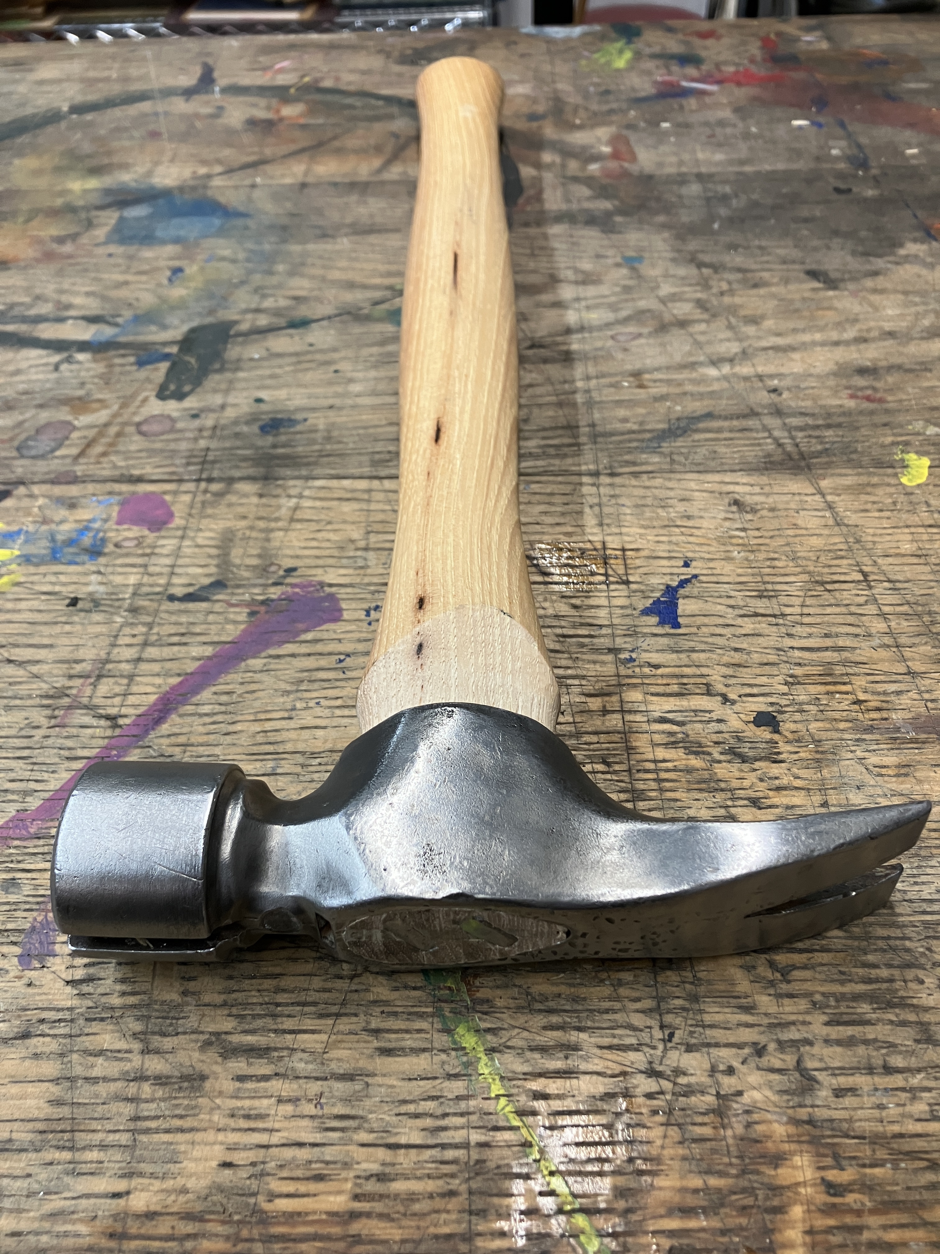
Scrounging through my dad’s cast off tools, found this framing hammer. As I was never really strong enough to swing a 24oz framer when I was a carpenter, I never bought one (I used a 16oz hammer with a long handle, because m*v^2). Now that I have no use for it and am even weaker, seemed like a good time to take it home and give it a new, coddled life. Replaced dad’s splintered and grey handle with a brand spanking new one.
18
19
20
21
22
23
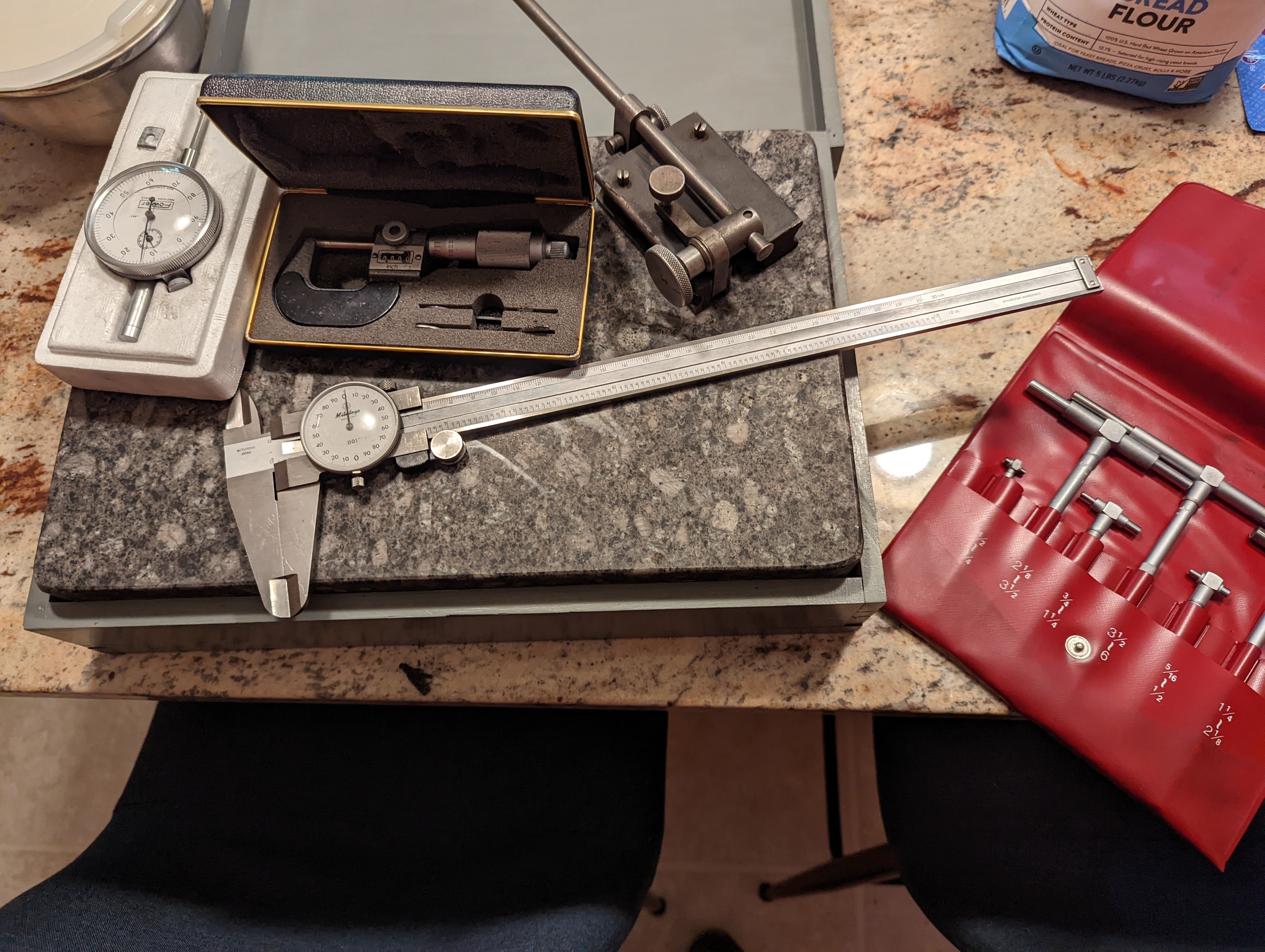
I scored a mitutoyo dual caliper, micrometer, and bore gauges. I also got a fowler indicator, stand, and surface plate. Managed to get everything for $50. 
Also pictured is the poolish I have fermenting for bread I'm going to make tomorrow.
24
25
view more: next ›