Editor's note: I can't post pictures from my Lemmy.world account. I presume that recent trolling-attacks vs Lemmy.world have to do with this restriction, so I'll use my Lemmy.ca account for this post.
Today is a "Sidenote" for my "Beginner Series", because its not a particularly scheduled discussion point. I was browsing the internet for some documentation when I found Microchip's Signal Chain Design Guide.
Yes, this is marketing material. But its well written and covers many important concepts for beginners. Again, the PDF is here: https://ww1.microchip.com/downloads/en/DeviceDoc/21825g.pdf
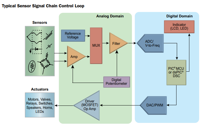
At the crux of the 'Signal Chain' is the following diagram:

Many, many applications can be simplified down to this loop. Sensors provide a signal of some kind: changing voltages or currents as real life events happen. Temperature changes resistance and/or voltage of a thermocouple, pressure changes resistance of resistors as well. More complex sensors like IR Photodiodes will change their current due to the presence of light. (and that IR Photodiode may itself be encoded information: with lights turning on-and-off associated with machinery RPMs).
Whatever the "sensor" is, it may need analog processors to condition. OpAmps are the most common analog processor, but instrumentation amps, differential amps, and sometimes even raw BJTs are used for this step (when high-frequency is needed, such as amplification of radio signals). There's a side note here about digital-potentiometers and their ability to calibrate analog bits of your circuit, but calibration can be skipped if you don't care much about accuracy.
In particular: whatever your "signal" originally was needs to be converted into a voltage of the appropriate size for your ADC. For example, a capacitive touch sensor can track the human-body (fingers) moving across different electrical pads. This "signal" is watching for the change of capacitance over different electrical lines. But "capacitance" isn't voltage. Instead, you need to inject small amounts of current into the various pads while measuring their change-of-voltage over time, which converts the "change of capacitance" into a "change of voltage" formula, thereby allowing later stages to operate upon your data.
Once the signal is processed to appropriate levels of voltage and/or current (or if you're lucky enough: the raw signal is good enough without need of preprocessing), then you can feed it into an ADC and digitize the signal.
Once the signal is in digital form, you write a computer program to analyze and manipulate the data. For many, the data will remain in digital form perpetually, sent out over WiFi, Bluetooth, or perhaps to a MicroSD card for recording. But for others, the job is not done yet. The combined sensor data goes into an algorithm to determine actuator outputs.
Those actuator outputs leave in either PWM form or DAC as an analog signal directly. Alas, microcontrollers usually have weak pins, so output processing and amplification is needed to increase power levels to appropriate voltages and/or currents.
Finally, those voltages and/or currents affect an actuator. That could be a servo, a motor, LEDs to blink or really anything.
While these steps are individually pretty simple, as a whole they constitute a pattern and architecture that matches a huge number of electronic designs. Your thermostat (temperature sensor -> microcontroller -> turn furnace on or AC on). Drones (accelerometers to measure bearings in space - microcontroller -> motor controls), motor controls (sense current through motor to estimate torque -> microcontroller -> BLDC Motor signals), and more.

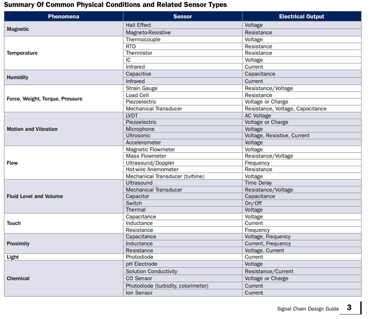
This page summarizes the sensors available from Microchip. And remember, this is just one company. There are plenty of sensors available around the world in many other forms.
As far as actuators... Microchip doesn't make too many of those. But motors, speakers, MEMS, refrigerators... anything you can hook up to electricity is something you can control with a microcontroller.


I realize this story is about the ESP32-S3, but the OTHER board discussed in that article is way more intriguing to me.
Wait, wut? They've got an i.MX unit? Well now I'm super intrigued. I've posted about the difference between Microcontrollers and Microprocessors in my guides. But the i.MX series from NXP tries to toe the line inbetween the two categories. A Cortex M7 though is still solidly "Microcontroller" to me, but any i.MX will intrigue me because its specs are incredibly high for a uC (or incredibly low-power for a uP).
With regards to Arduino form factor... the size roughly compares to 3x AA NiMH cells or larger 18650 Li-ion cells. Its a good size for portable applications, though a bit larger than something you'd reliably put inside a pocket (big pockets can probably fit Arduino form factor + batteries though).
Adafruit themselves seem to be most interested in the Cosplay-electronics community, so something like this would be a wearable that you'd hide in your costume somewhere. (Ex: controlling the lights to an Overwatch costume or other "techie" video game costume that needs a lot of lights, fiber optics, and the like).
In any case: that's three boards with three different sets of capabilities: from the lowly RP2040, to ESP32-S3, to i.MX Cortex M7 "crossover" chip.