[-] [email protected] 2 points 1 year ago* (last edited 1 year ago)

There is a zmk pull request open that adds split encoder support. If you use that to build your firmware if should work.

To be honest I have not tried it with this board so technically one scrollwheel is not working right now. Though I'll change that soon. I used a fork that supports split encoder with zmk on my sofle and it worked, so you could use this config for some inspiration (here: https://github.com/dnlbauer/sofle-zmk-config).

[-] [email protected] 2 points 1 year ago

looks great! what did you use to design the case and and how did you make this rough surface finish? It looks very good on the outside and will be good at hiding scraches!

[-] [email protected] 3 points 1 year ago
[-] [email protected] 5 points 1 year ago* (last edited 1 year ago)

The main lesson I learned was probably to start thinking "in hardware" and not software. Like you design something and it fits on paper but in reality, it might not be ideal. For example, my diode placement is very close to the hotswapsocket (i fixed that for rev 1.1). On paper it war fitting, but its kinda hard to solder when you need room for your solder iron in between - this is something kicad won't tell you.

[-] [email protected] 1 points 1 year ago* (last edited 1 year ago)

Haven't tried regular-sized choc switches before, but they should work. One thing to consider would be that with the heigher switches, the scroll wheel might be harder to reach with the thumb because it might be physically hidden behind enter/space. Should not be a problem if you are used to use the index for the wheels though.

[-] [email protected] 2 points 1 year ago

I use my thumbs for the scrollwheels. My previous build was a sofle but the knobs always bothered me. They stick out too much, make it hard to transport the keyboard and I got into a habit of turning them with my thumb+index, so leaving the home row. With the wheels, using them feels much more natural!

[-] [email protected] 1 points 1 year ago

yeah they are a bit expensive. But they are worth it imho. Scrolling with the thumb on them feels very natural and the height is very similar to the chocs!

192
submitted 1 year ago by [email protected] to c/[email protected]

My first design! Github link to the repo with pcbs and 3d printed components: https://github.com/dnlbauer/corax56-keyboard

[-] [email protected] 2 points 1 year ago

I just kept the default value (I think its 0.2mm) between traces. I could probably double it at some points where multiple traces are bundled though. Thanks for the hint!

[-] [email protected] 2 points 1 year ago

thanks for the imput. Do you mean I should just place some random vias to connect both sides of the ground plane? To be honest, I dont understand exactly what this ground plane is used for since none of the traces actually connect to it. Is it merely for shielding against signal noise?

[-] [email protected] 1 points 1 year ago

Hey, unfortunately erdogen, which I used to generate the starting point for the pcb does not generate a schematic file. It only generates the PCB and ratsnest for the footprints. So I dont have one. I think I could create one though. Mind telling me what this is used for and why one should have one?

[-] [email protected] 1 points 1 year ago
[-] [email protected] 2 points 1 year ago* (last edited 1 year ago)

fixed the domain. thanks for pointing that out!

If you are interested in the design process, I can highly recommend the tutorial series by FlatFootFox here. It was a great resource for me to get started. https://flatfootfox.com/ergogen-introduction/

44
submitted 1 year ago* (last edited 1 year ago) by [email protected] to c/[email protected]

Hey everyone!

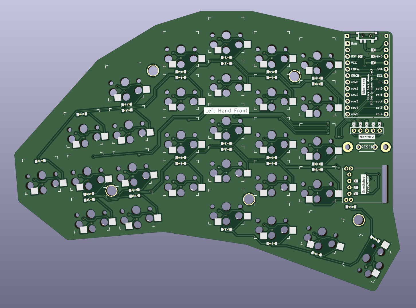
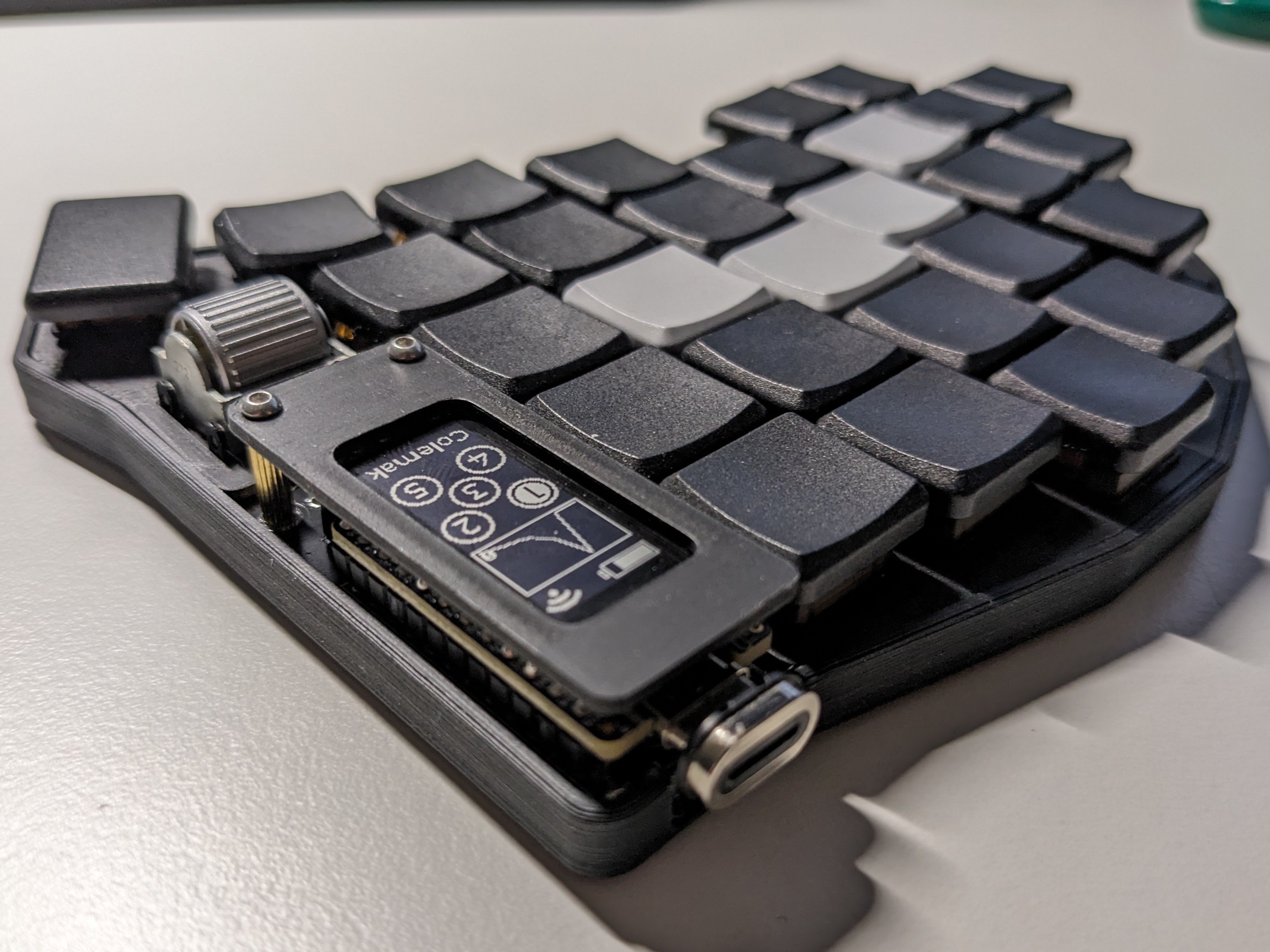
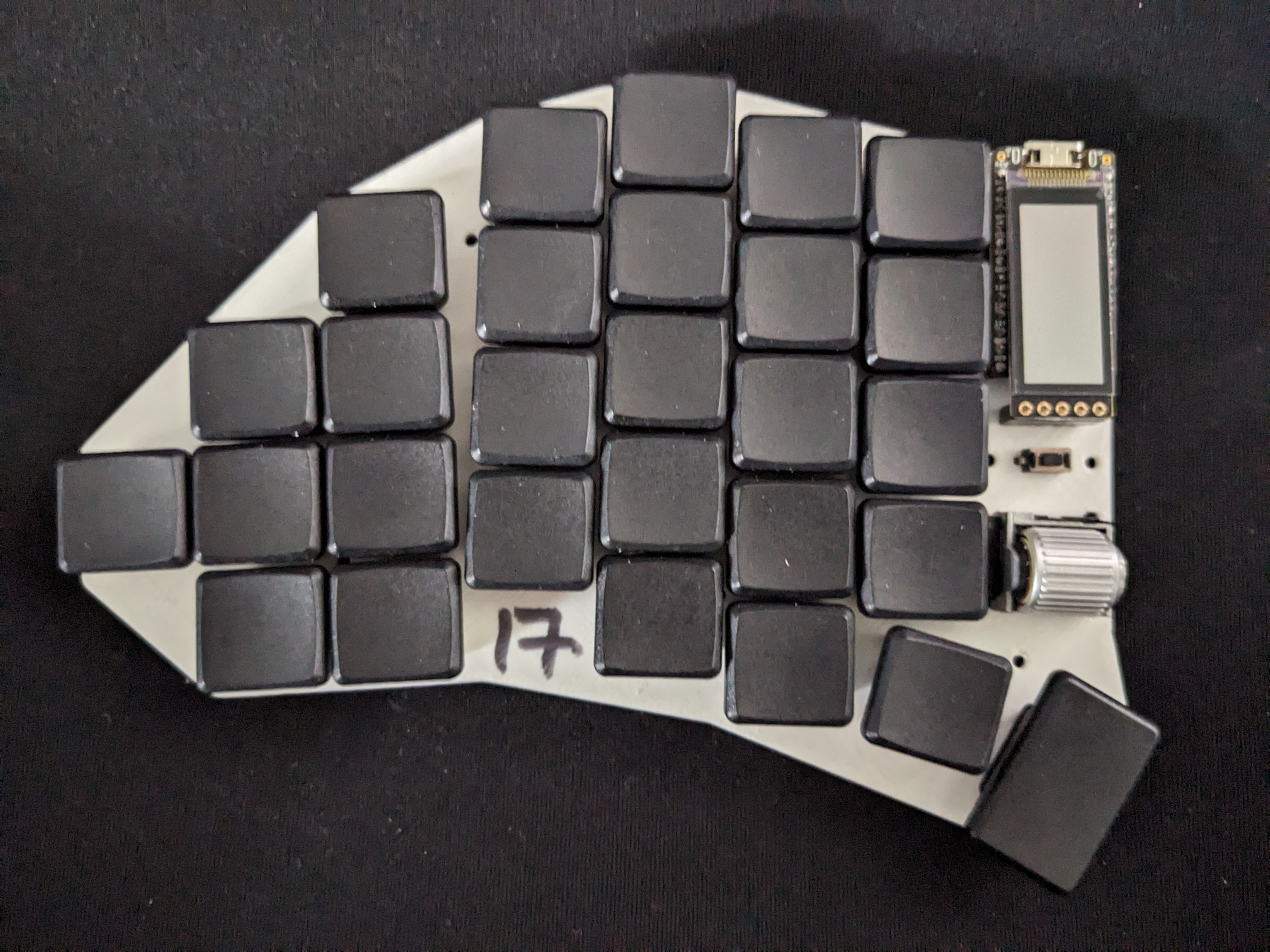
I jumped into the ergomech rabbit hole sometime last year and after using a sofle as my daily driver since then, I now decided it's time to build my own "thing". After going through endless revisions to figure out what I actually want, and trying to learn how to trace PCBs, this is what I have come up with: A choc-spaced 56 keys wireless build with a scrollwheel and some staggering.

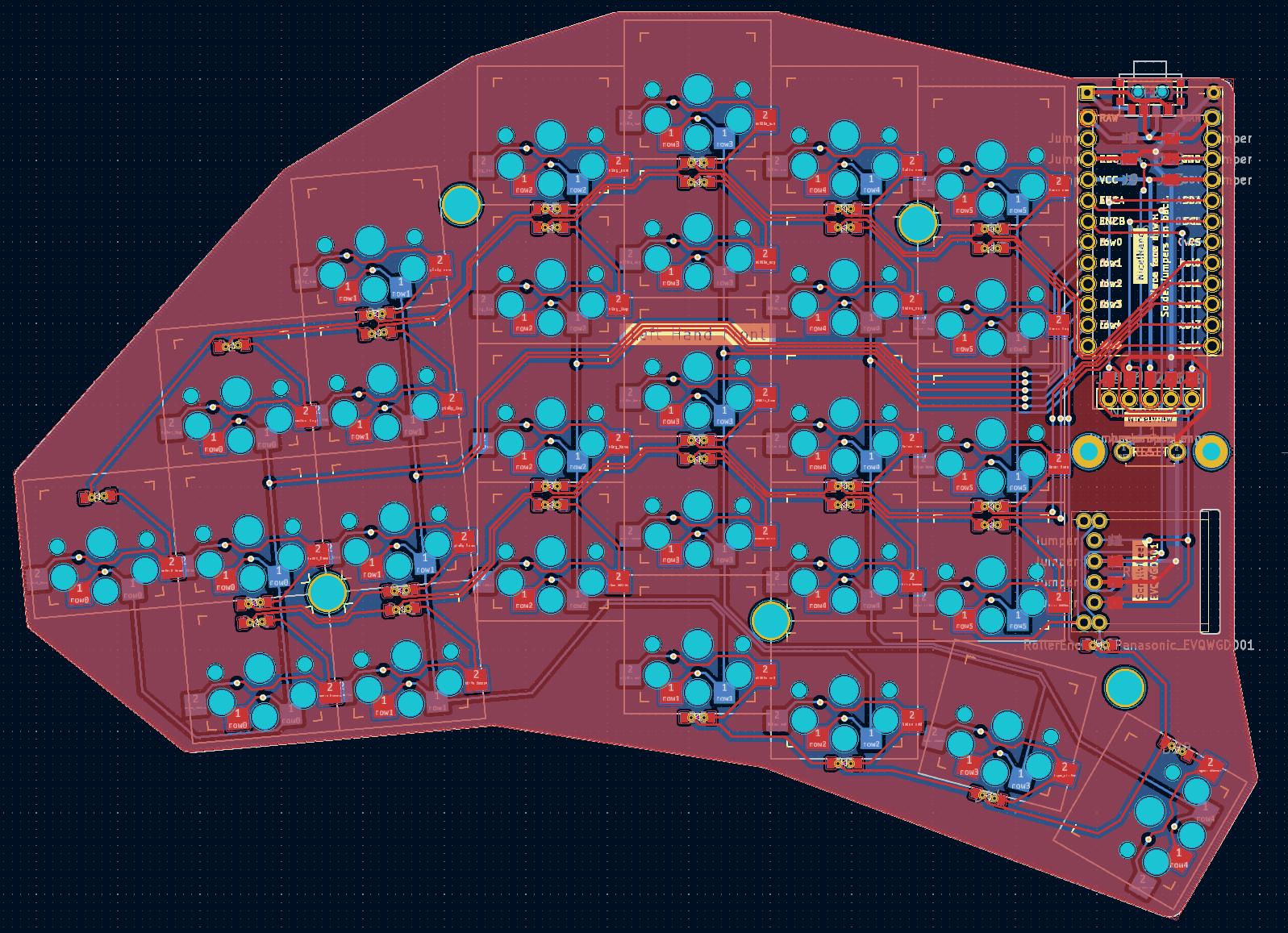
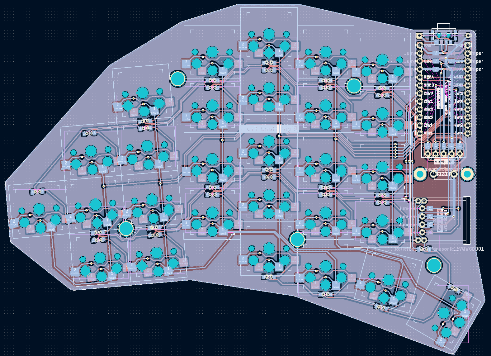
It's a reversible PCB. To make this work with single pin hole for both sides, I used jumpers for pins that can not be set in software (VCC, GND, RST). For rows/columns, I plan to do a different mapping in software to not have a jumper for every single pin.

All files including the kicad_pcb and ergogen config are available and open source at github: https://github.com/dnlbauer/splitkeyboard .

However, this is the first thing I ever designed. Therefore, I was hoping if you guys could have a look at the PCB before I get it etched and point out if there are any obvious errors?

Of course, I am also happy about any feedback in general. :)

view more: next ›

dnl

joined 1 year ago