HVAC/R technicians and affiliated trades

91 readers
1 users here now

This is intended to be for hvac technicians and with hvac technicians in mind. Please refer to c/hvacadvice for out of the trade conversation, requests for help and whatnot.

founded 1 year ago
MODERATORS
1


cross-posted from: https://lemmy.dbzer0.com/post/26703241

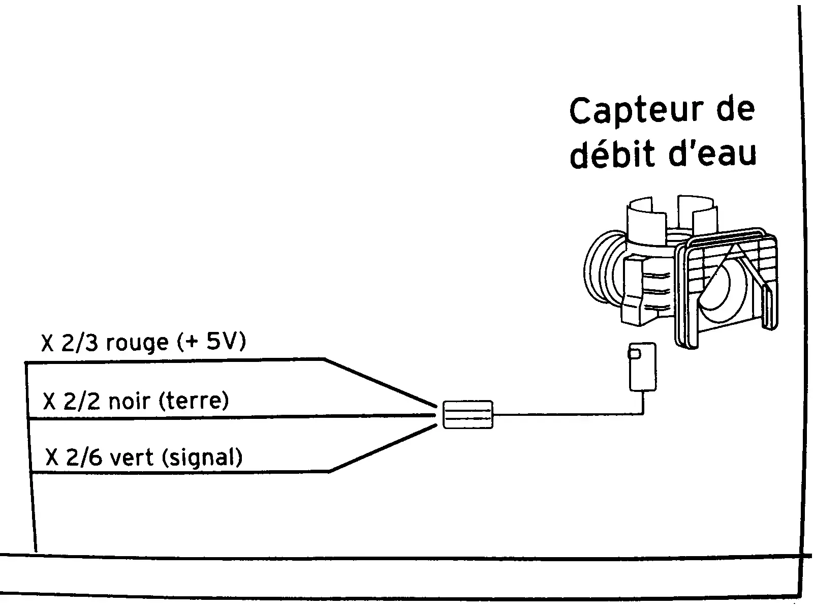
This diagram is from the service manual of a combi boiler. It’s a flow sensor which detects whether hot water is running, which is then used to trigger on-demand heat and switch a diverter to take radiators out of the loop.

In English, the diagram shows:

  • X ⅔ red wire (+5V)
  • X 2/2 black wire (ground)
  • X 2/6 green wire (signal)

I need to know what those fractions mean. I took the voltage measurements in this video:

I cannot necessarily trust the model in that video to have the same specs as mine. My voltmeter detected 4.68 V on the red input wire showing that the sensor is well fed. The green “signal” wire is supposed to be 0 V at rest and 2 V with water running (or I think the reverse of that is used in some models). In my case the green wire is ~1.33 V at rest and ~0.66 V when water is running. I need to know if these readings are normal as I troubleshoot this problem.

update


@[email protected] gave the right answer. Someone in another cross-post helped solve the underlying problem.

2


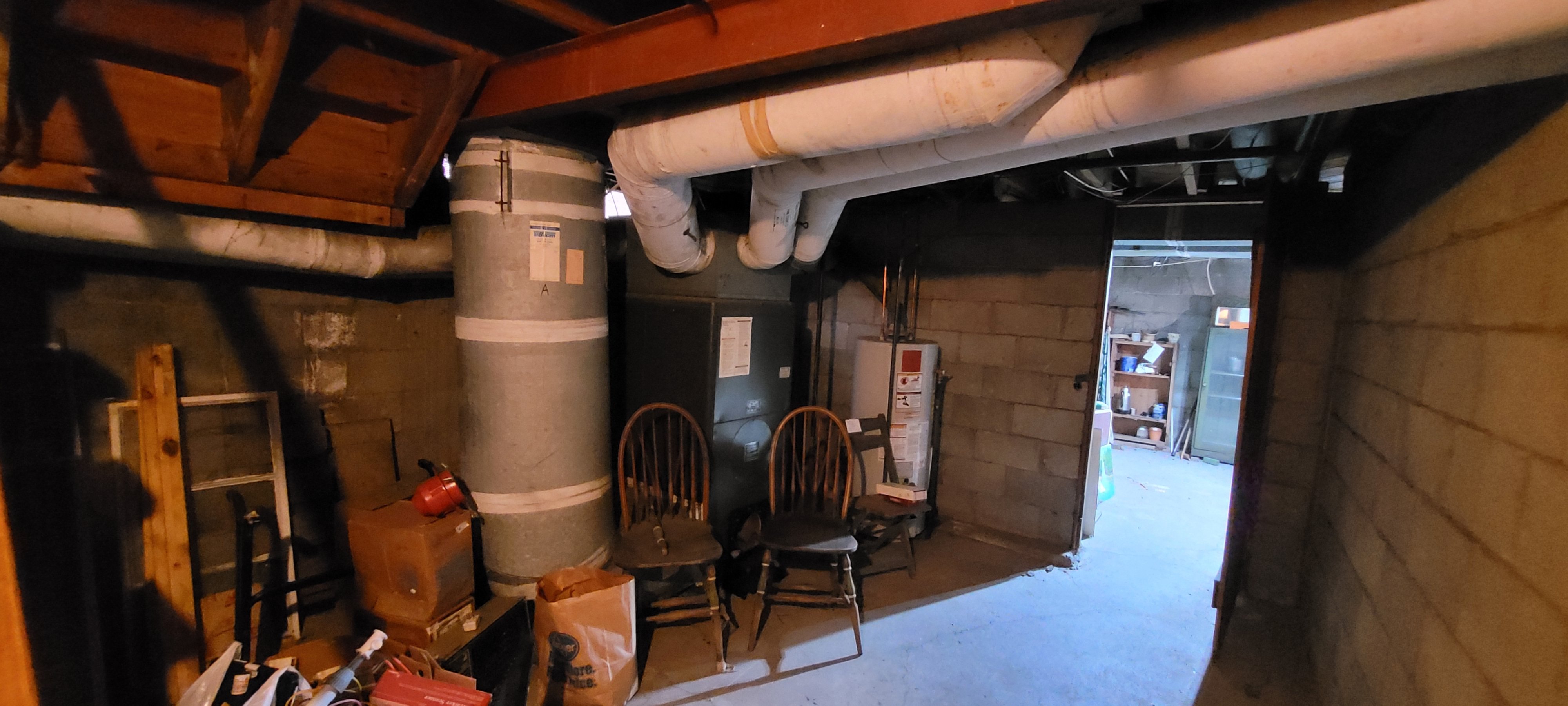
Hello, I am getting estimates for updating the heating/cooling in my owner occupied 2 unit home. New York is offering incentives for switching away from natural gas so I'm hoping to get this done before winter. Each unit is about 1000 sq ft. Do these prices look about right? I have no knowledge about any of this, just want to make sure I'm not being taken for a ride. Thanks!

3


I'm not in HVAC but I loved these photos

4
 
 
5
 
 
6
 
 
7


If something happens to the main r/hvac on reddit, this is here as a new version, I guess.